Numerical analysis is a design tool well-established in many branches of engineering, and geotechnics makes no exception. However, soil behaviour differs from a typical construction material for the high non-linearity shown even at the smallest loading stages. In addition soil can show properties such as intrinsic anisotropy, viscosity, collapsability, expansivity and bonding amongst many others. Constitutive models taking into account some of the relevant features of soil behaviour usually need extremely complicated implementation strategies based on iterative integration schemes.The definition of suitable initial conditions and loading history makes numerical analysis for geomaterials even more complex, as they strongly influence soil strength and stiffness and therefore represent important factors to be taken into account. For all the above reasons, numerical analysis for geotechnical engineering turns to be an extremely challenging task for computers, and it is only recently that the required CPU power has been made available by personal computers.
However, the fact that enough computational power is nowadays accessible does not imply that numerical analysis is readily usable by any geotechnical engineering because of the high level of specialization required to operate it. Specialists at WeSI Geotecnica have a long-term experience of implementation, validation and use of advanced constitutive models, and they have been dealing with numerical analysis for many years both in research and production. This makes WeSI Geotecnica the ideal partner for assisting the design engineer with geotechnical analysis.
Geotechnical analysis can be used whenever an accurate prediction or back-calculation of displacements is sought. WeSI Geotecnica has a long record of successful use of numerical analysis in different classes of geotechnical engineering problems, the most common of which are listed below.
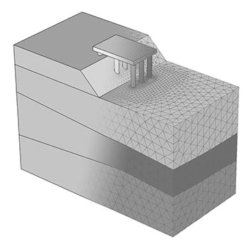
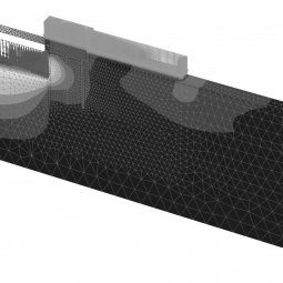
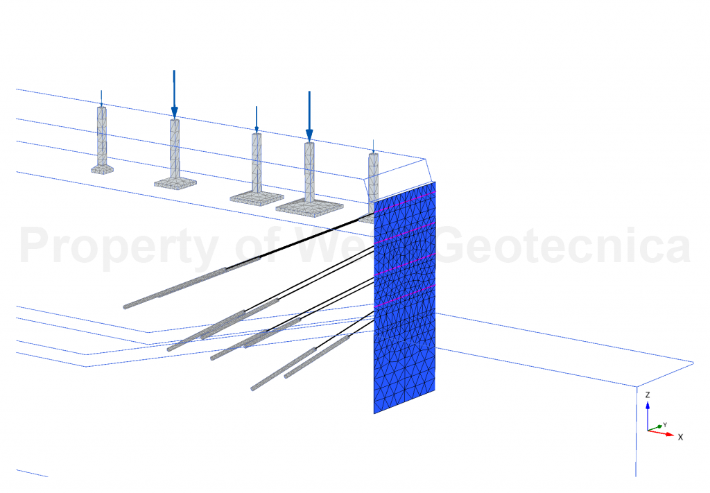
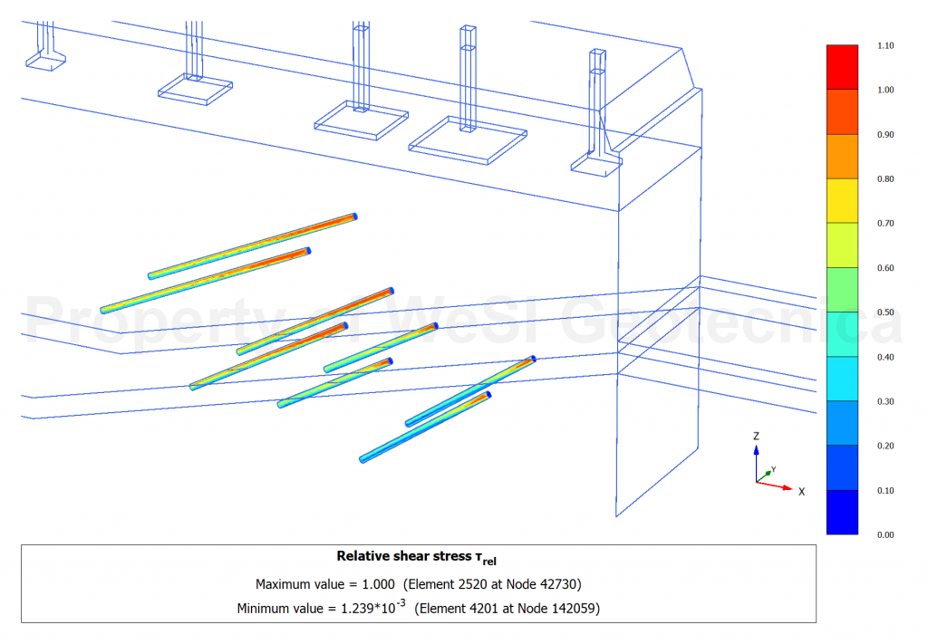
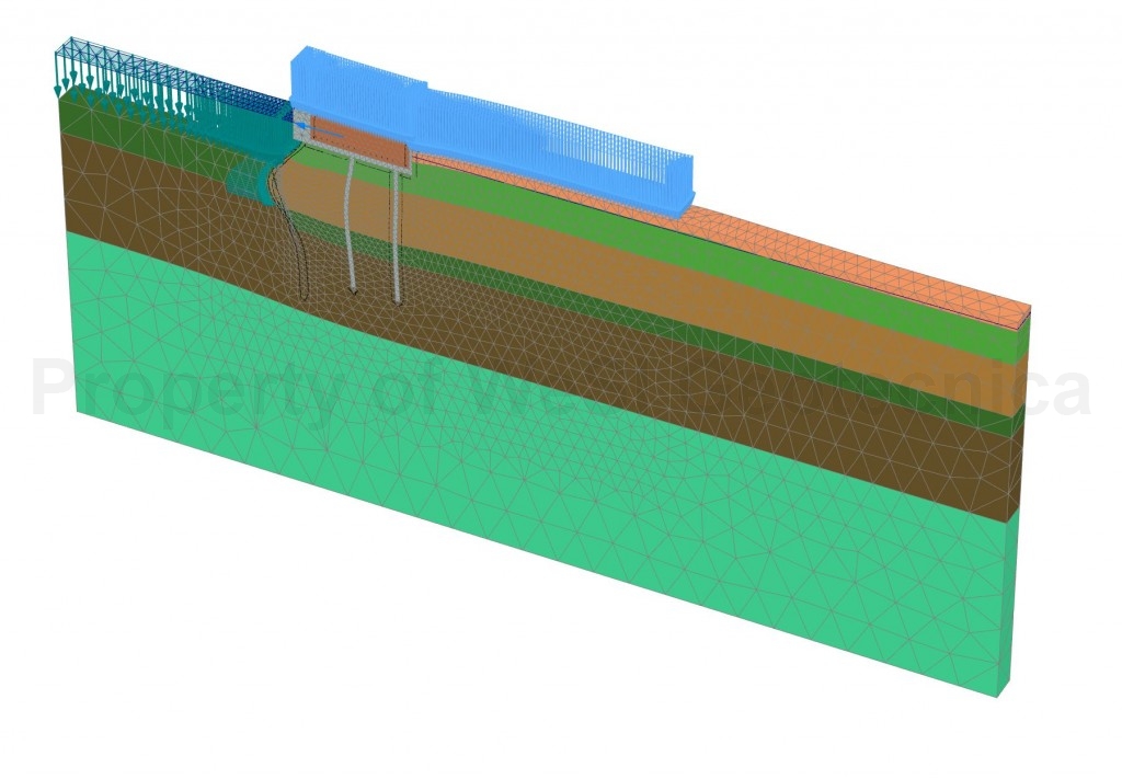
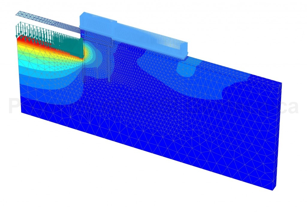
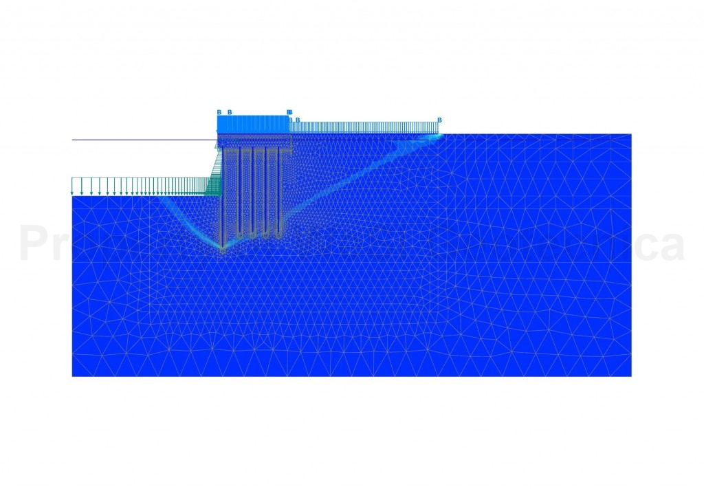
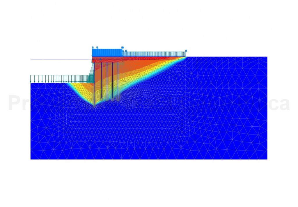
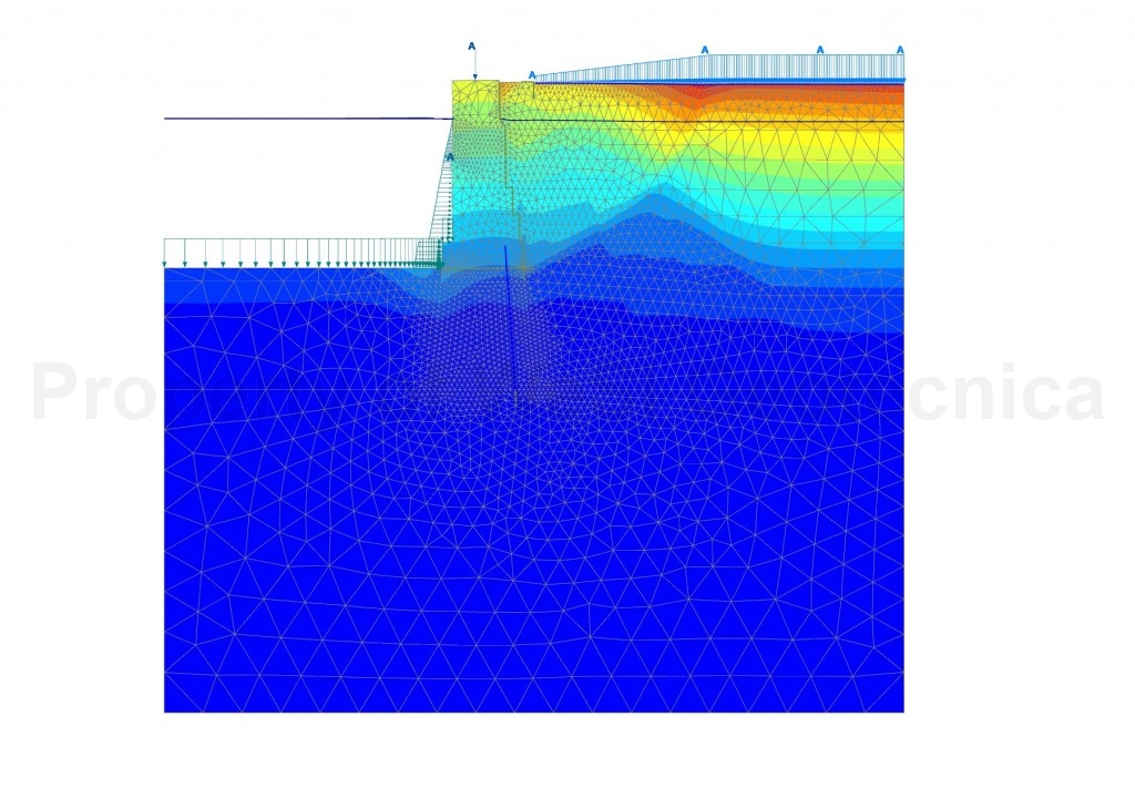
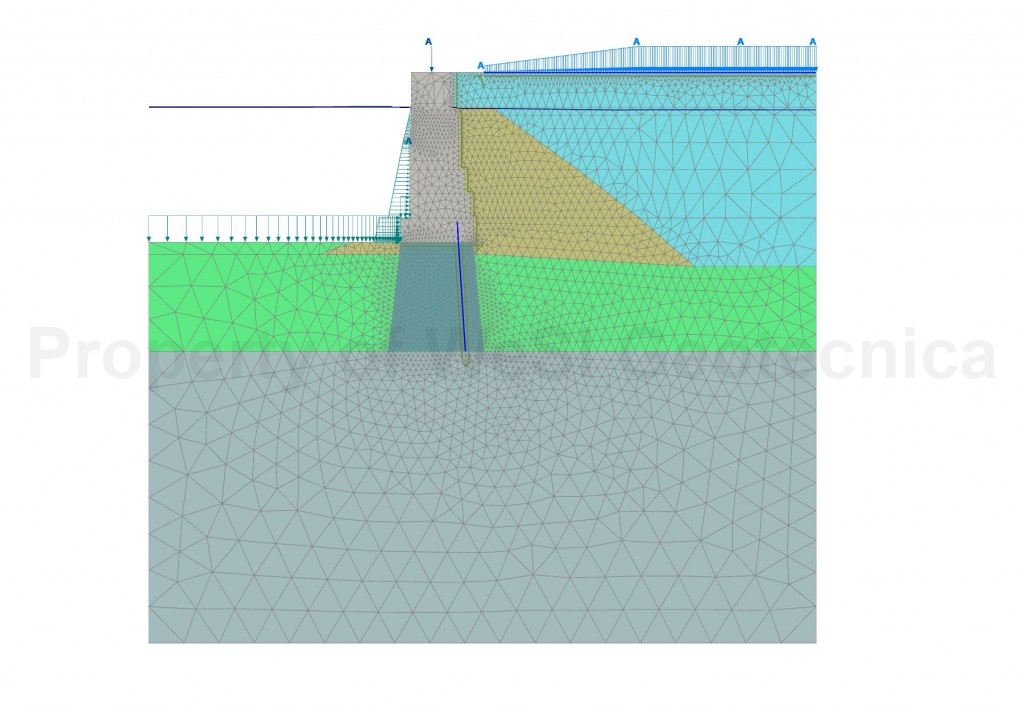
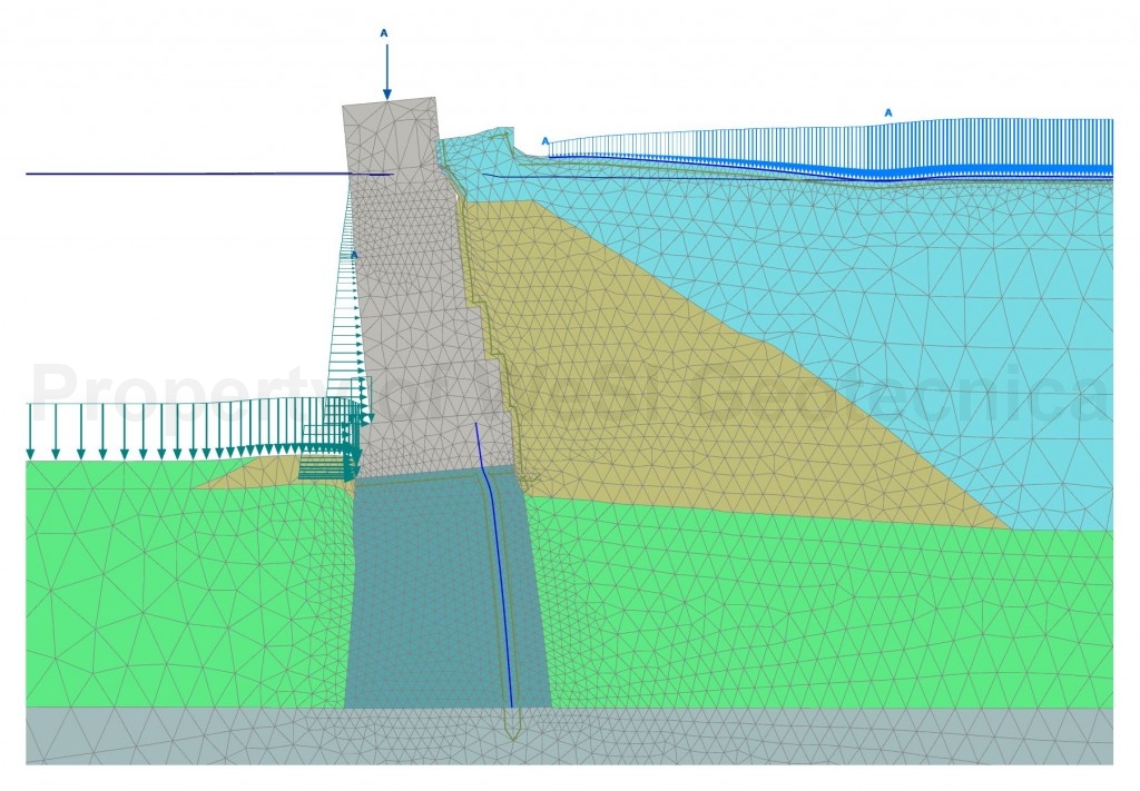
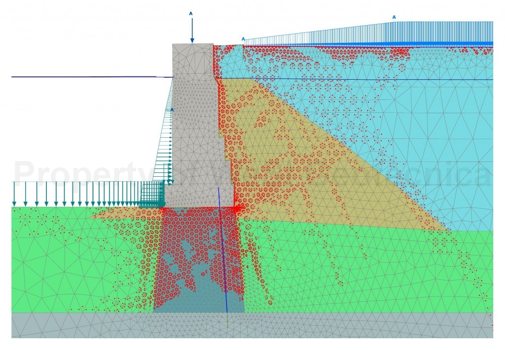
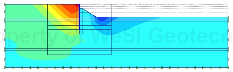
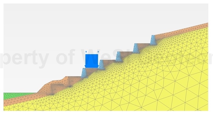
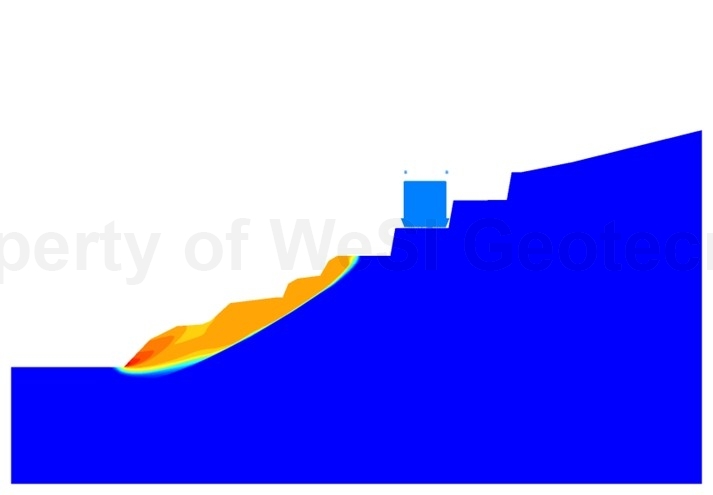
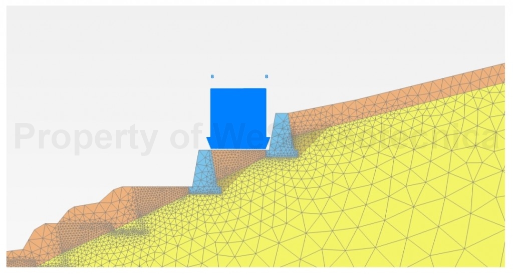
An earth retaining wall is a geotechnical structure designed to stand against the lateral forces induced by a different elevation in either natural ground or fill. The earth retaining structure normally includes a wall, which is often supported by additional structural elements such as ground anchors, props, reinforcing strips or nails, relieving platforms. The foundation load can be directly supported by the ground at its base or be transferred to depth through a load transfer mechanism such as the one provided by piles. Retaining structures broadly fall into two categories: freestanding walls, in which stability is mainly due to the self weight of the structure, and embedded walls, where stability is ensured by the passive resistance of the soil over the embedment depth. Particularly in the latter case, in addition to the assessment of the structural actions in the wall and reinforcing elements, an accurate prediction of magnitude and extent of ground movements is necessary.
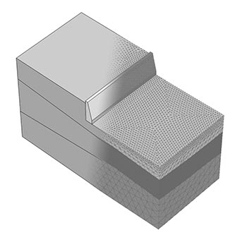 Design approach
Design of retaining walls has traditionally been carried out using simple calculation methods, e.g. Limit Equilibrium Method (LEM), stress fields or empirical approaches. Simplified methods have been adopted for free standing gravity walls, embedded cantilever walls, embedded walls with single anchor or prop and lately for reinforced or anchored earth. Because all of these traditional design methods are based on extremely simplified models or empirical rules, in many cases they fail in providing the engineer with all the desired information. For example, they often only provide partial indications of soil displacements and no information on the interaction with adjacent structures or services. Moreover, they always require plane strain geometries, simplified construction stages or boundary conditions for embedded walls. By using Finite Element Method the behaviour of retaining structures in service can be predicted, in particular by investigating the mechanism of soil-structure interaction. By adopting three-dimensional geometries, with a correct definition of boundary conditions and adequate constitutive laws, both serviceability and failure can be addressed with a suitable level of detail. The method can also predict structural and geotechnical behaviour for statically indeterminate cases, such as multi-propped or multi-anchored embedded walls, in which conventional design methods based on equilibrium cannot be employed.
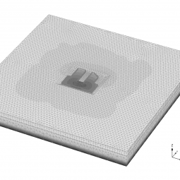
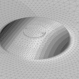
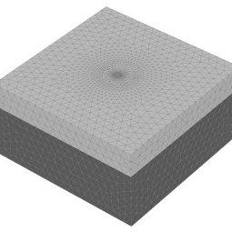
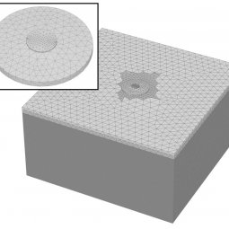
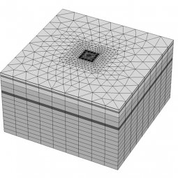
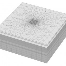
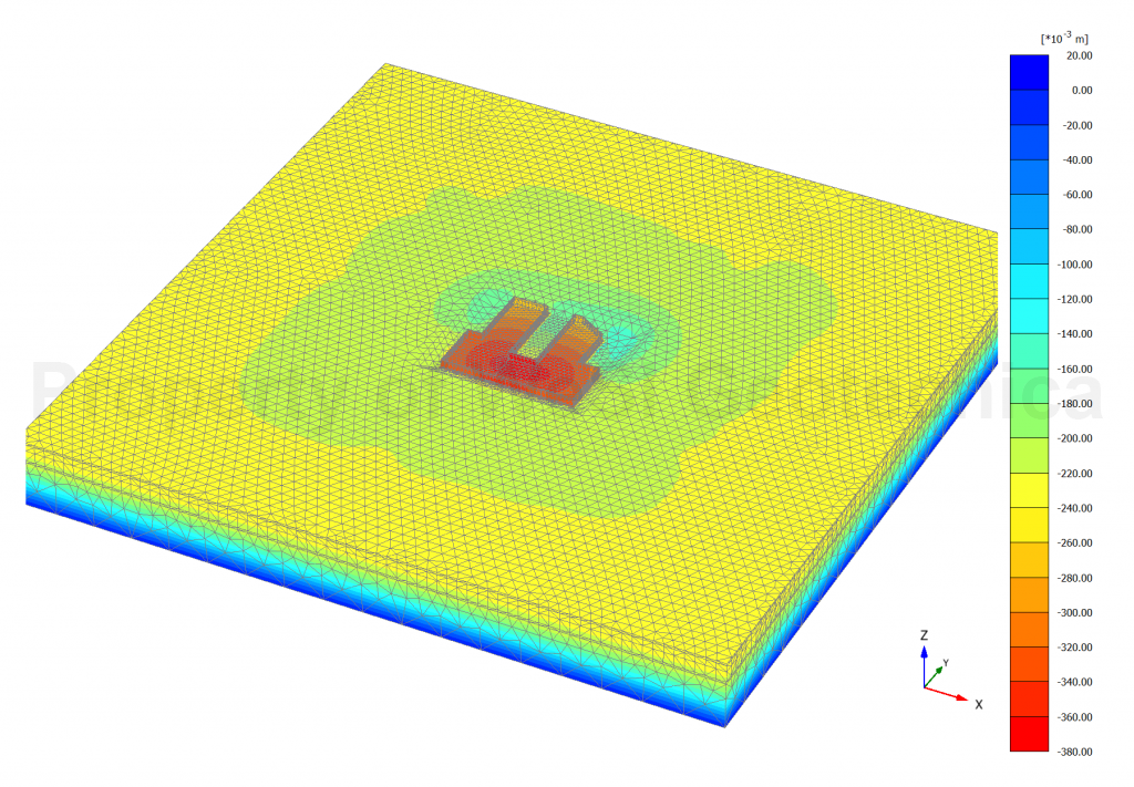
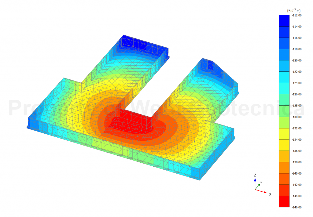
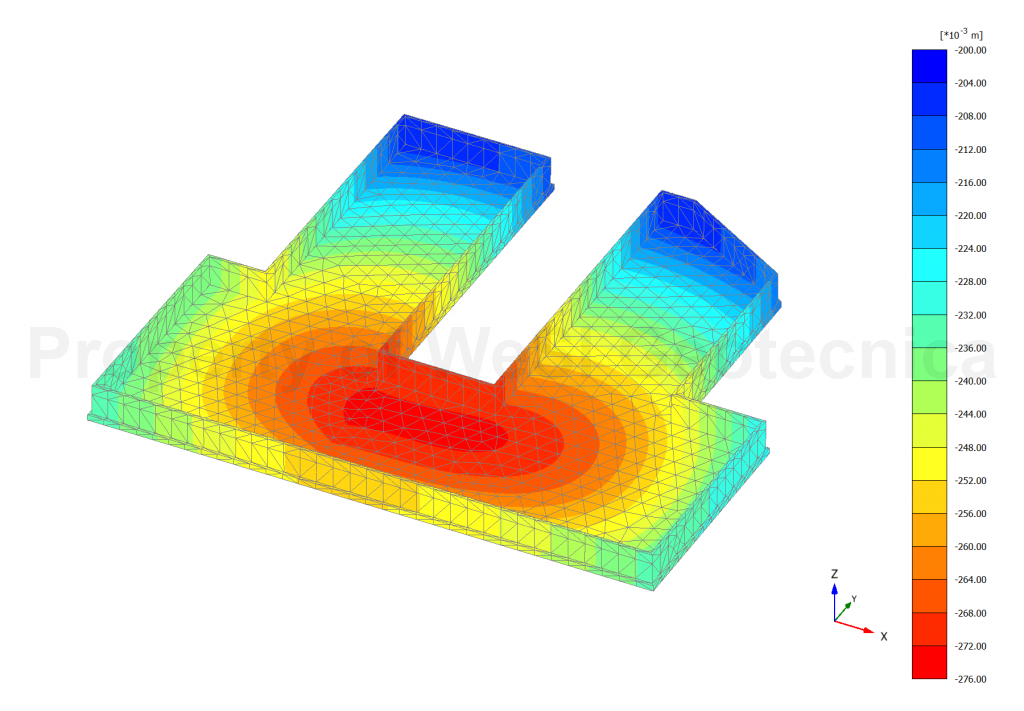
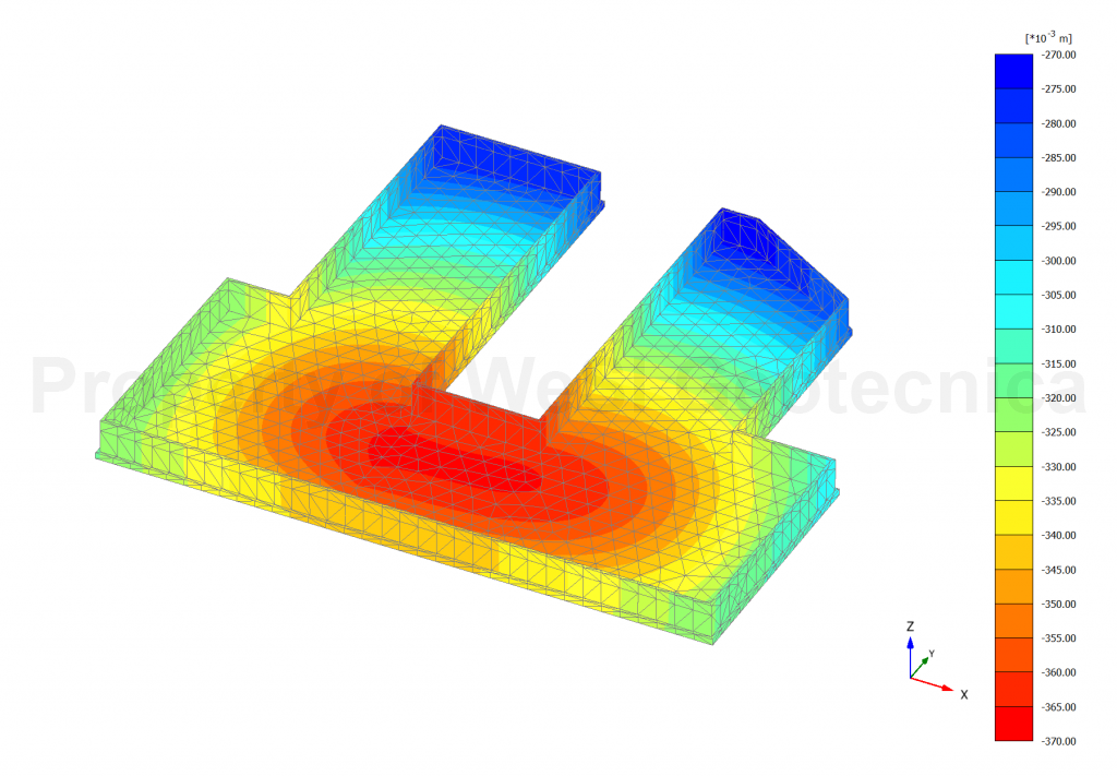
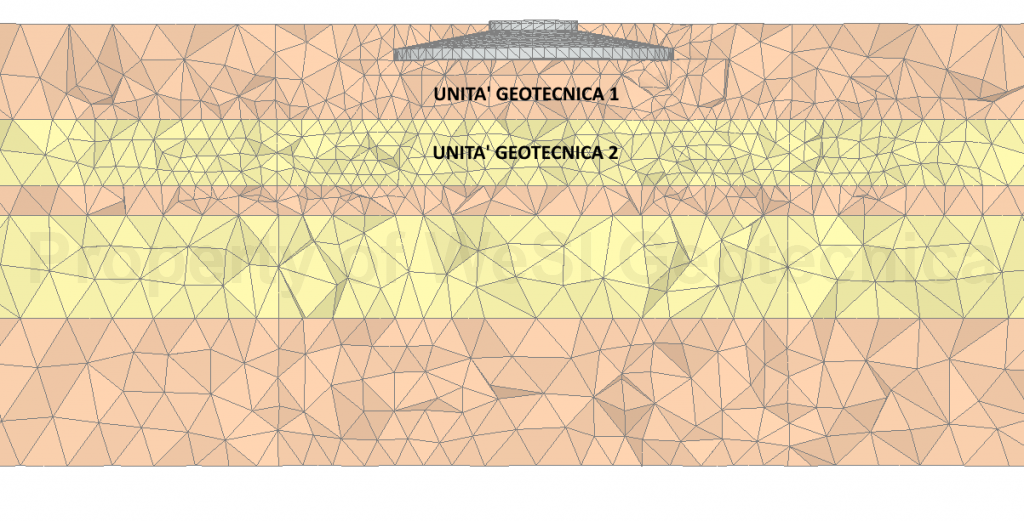
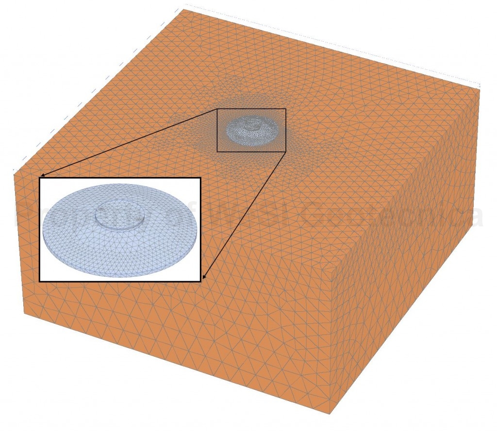
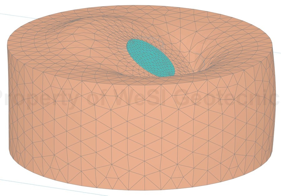
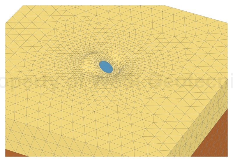
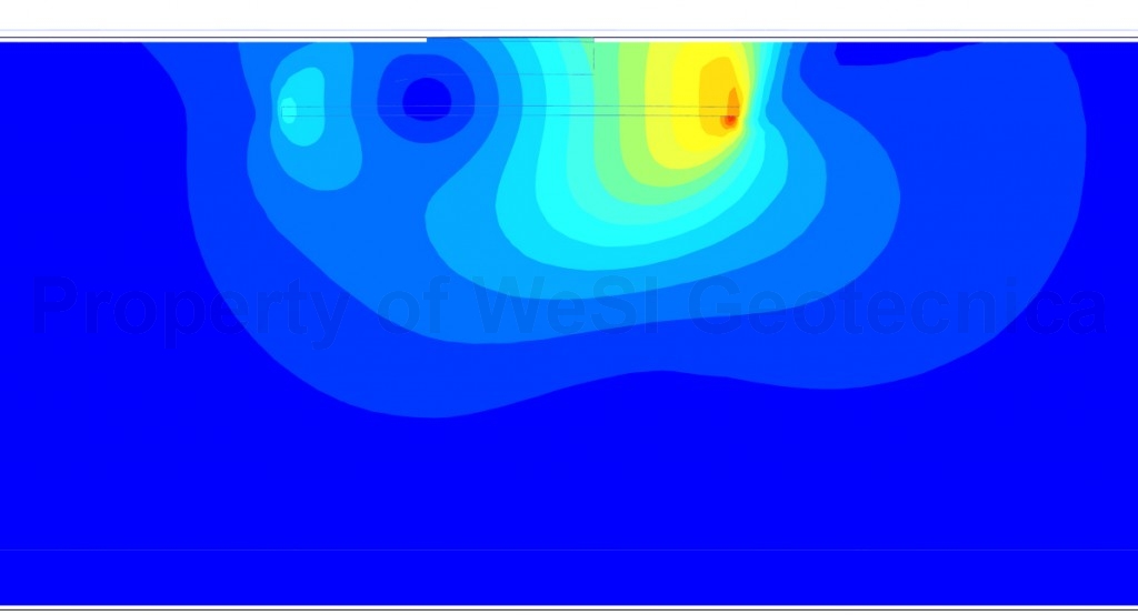
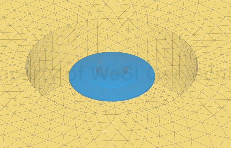
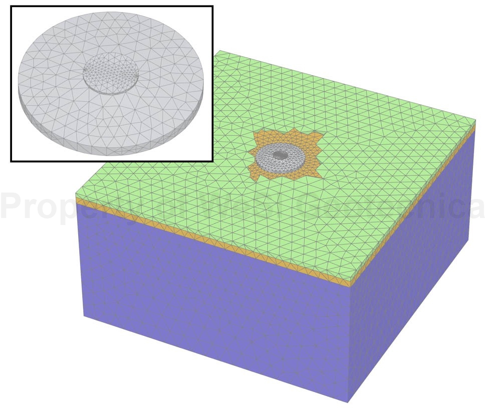
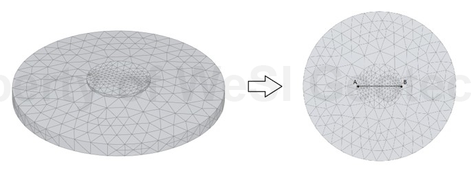
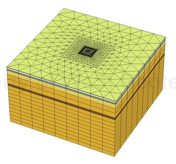
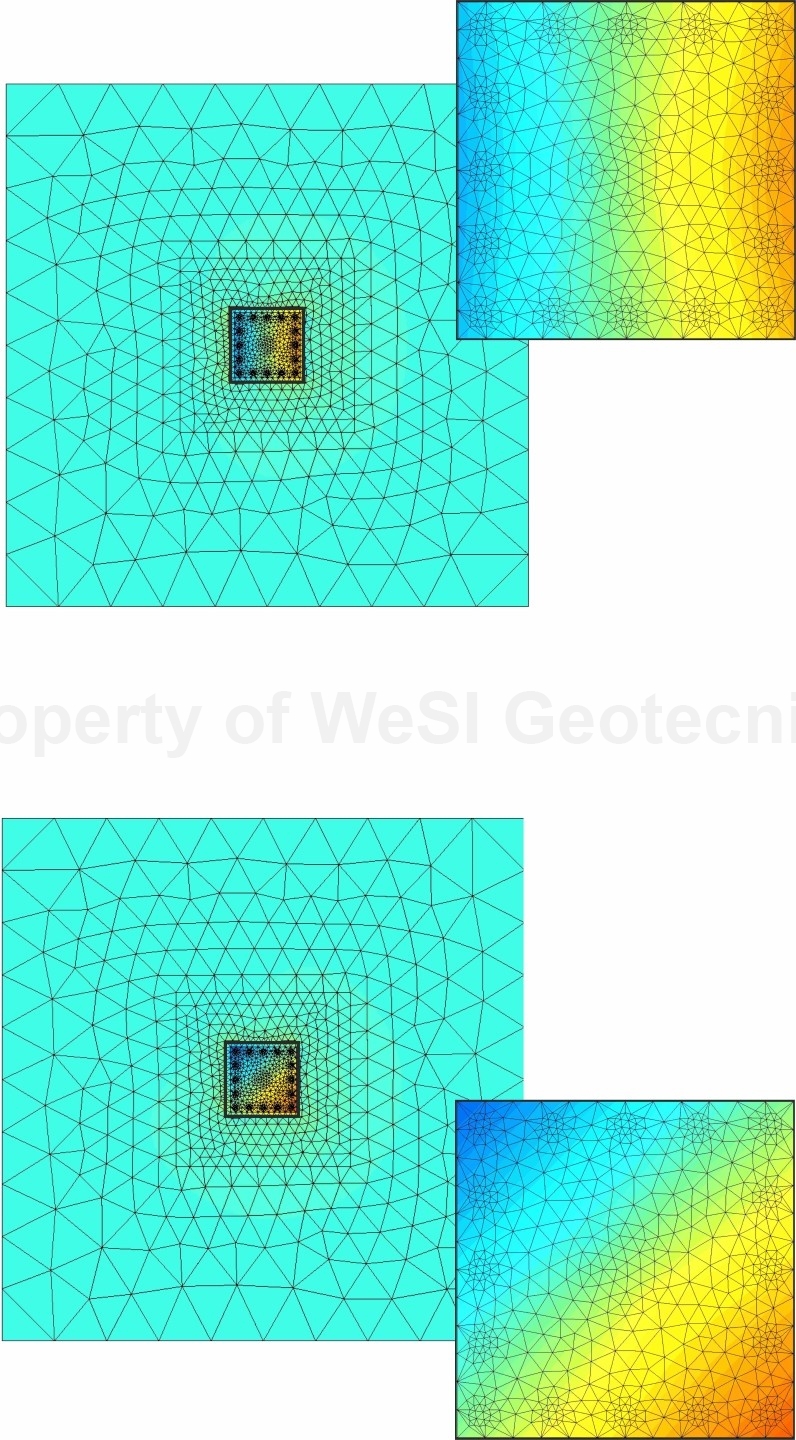
A foundation is the part of a structure which transmits loads directly to the undelying soil. If a soil stratum near the surface is capable of adequately supporting the structural loads it is possible to use either footings or a raft, these being referred to in general as shallow foundations. Conventional foundation design generally separates considerations on failure (e.g. bearing capacity, sliding), from soil deformations (i.e. settlement calculation). By referring to this uncoupled approach it is not possible to reproduce any load-displacements curve, but it is only possible to determine the ultimate foundation load and an initial slope for the load-displacement curve (as the settlements are usually calculated in service load condition). Various methods included in several standards and codes (e.g. Permissible Stress method, Limit State method) can be conveniently used to provide a safe design.
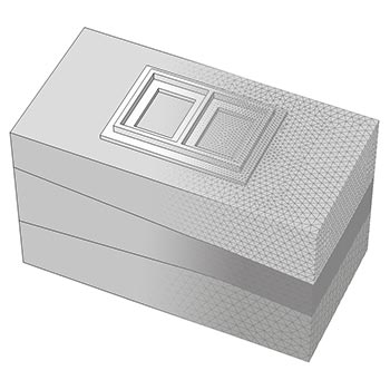 Design approach
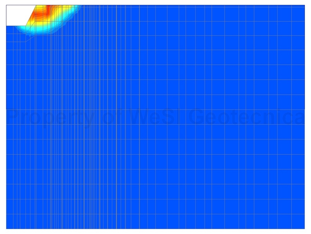
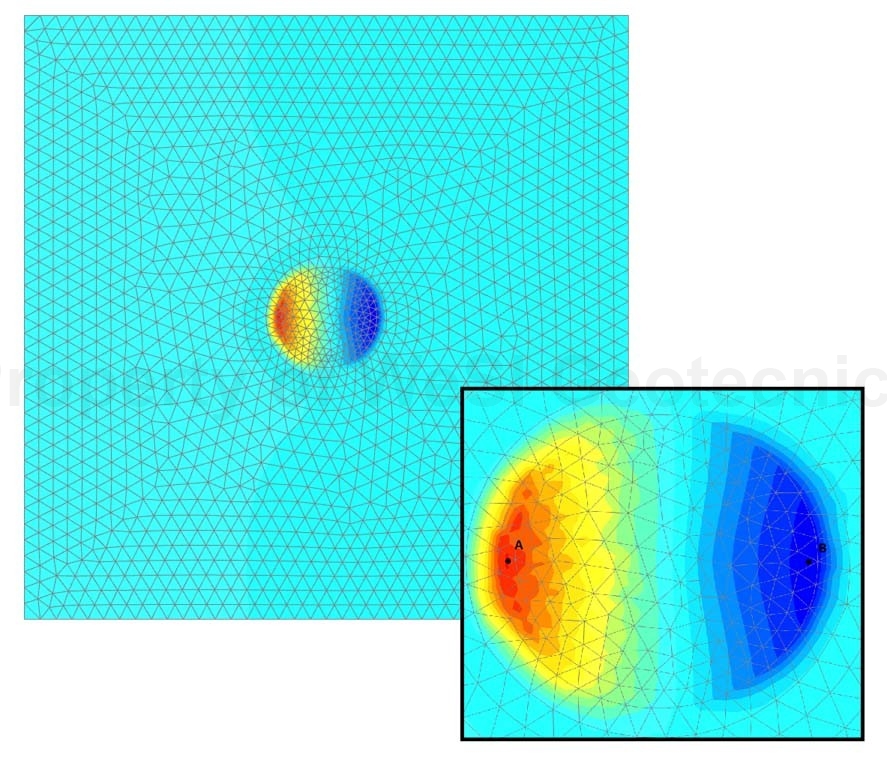
The calculation of bearing capacity for a shallow foundation has been traditionally based on limit analysis, where the soil is assumed to behave as an elastic-perfectly plastic material based on Mohr-Coulomb failure envelope for the long term, or on Tresca failure criterion for the short-term case. On the other hand, foundation settlements are predicted by using linear or non-linear elastic theory. Such design approach has been conveniently used for decades by practicioners, but conventional bearing capacity solutions can only be adopted for simple foundations resting on one homogeneous soil layer. Numerical analysis can take into account more complex foundation and soil geometries. Furthermore, it can deal with complex design load cases such as axial force, shear and bending moment combined together. The need of numerical methods is also apparent for time-dependent coupled problems in which the knowledge of the variation of bearing capacity with time is predominant, such as for foundations on soft normally consolidated clays. Conventional methods generally produce acceptable results for the average foundation settlement, but they fail in providing differential settlements or deformations under combined loading, usually completely ignoring the stiffness of the foundation and assuming a uniform pressure. Amongst others numerical approaches, a properly operated Finite Element analysis can overcome all those issues.
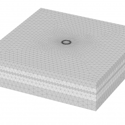
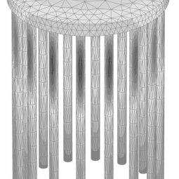
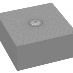
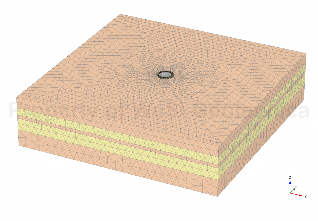
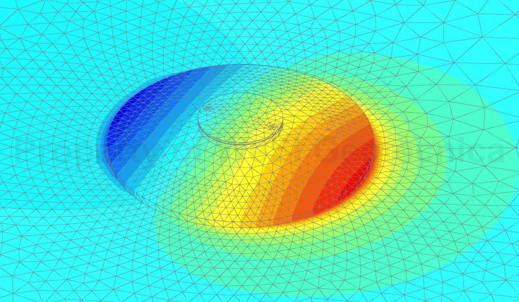
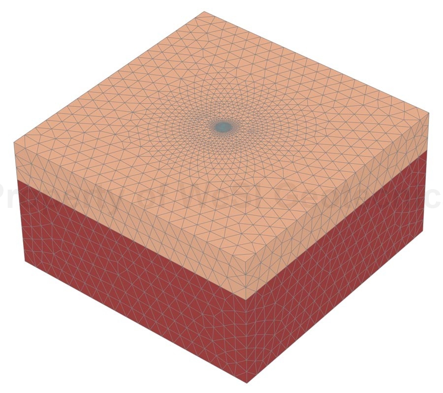
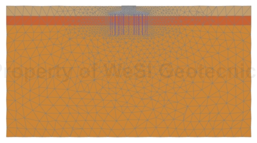
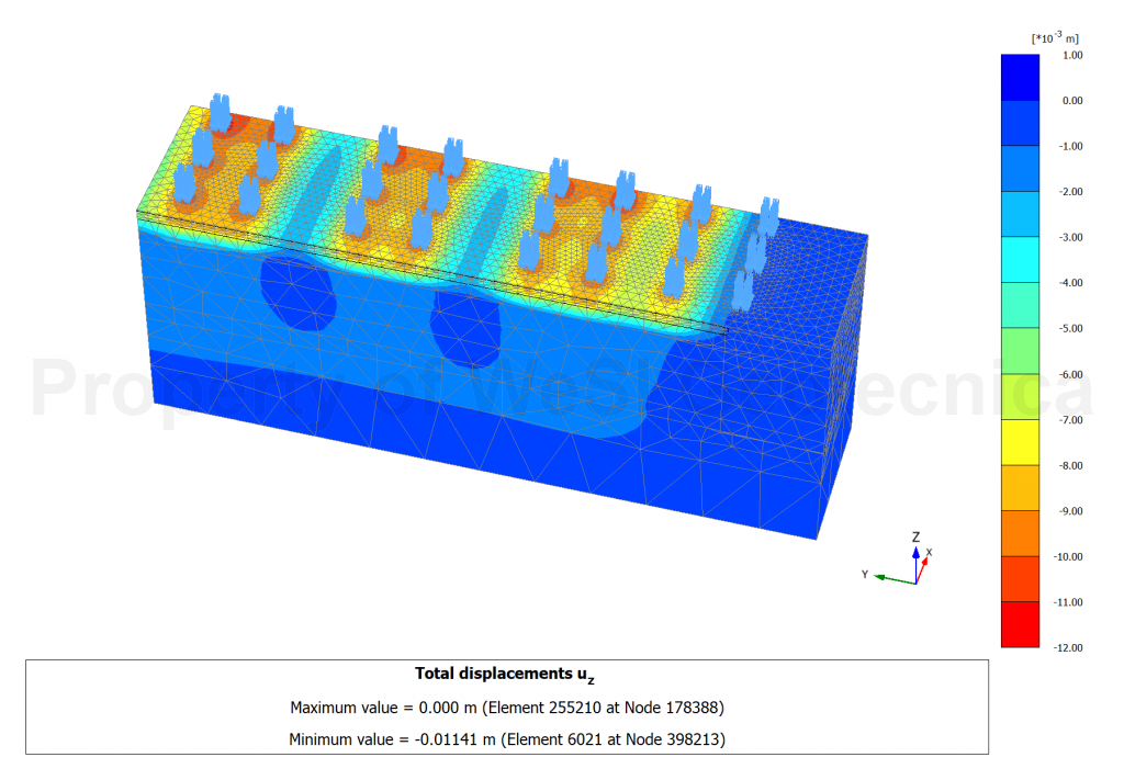
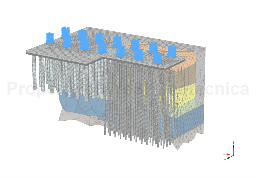
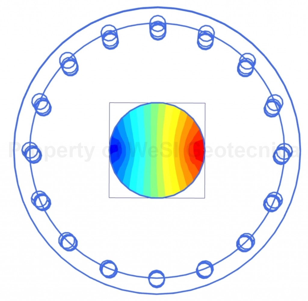
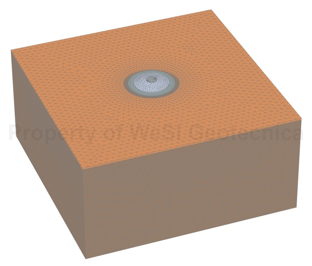
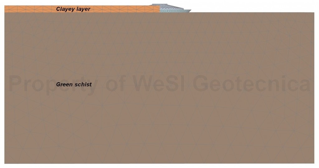
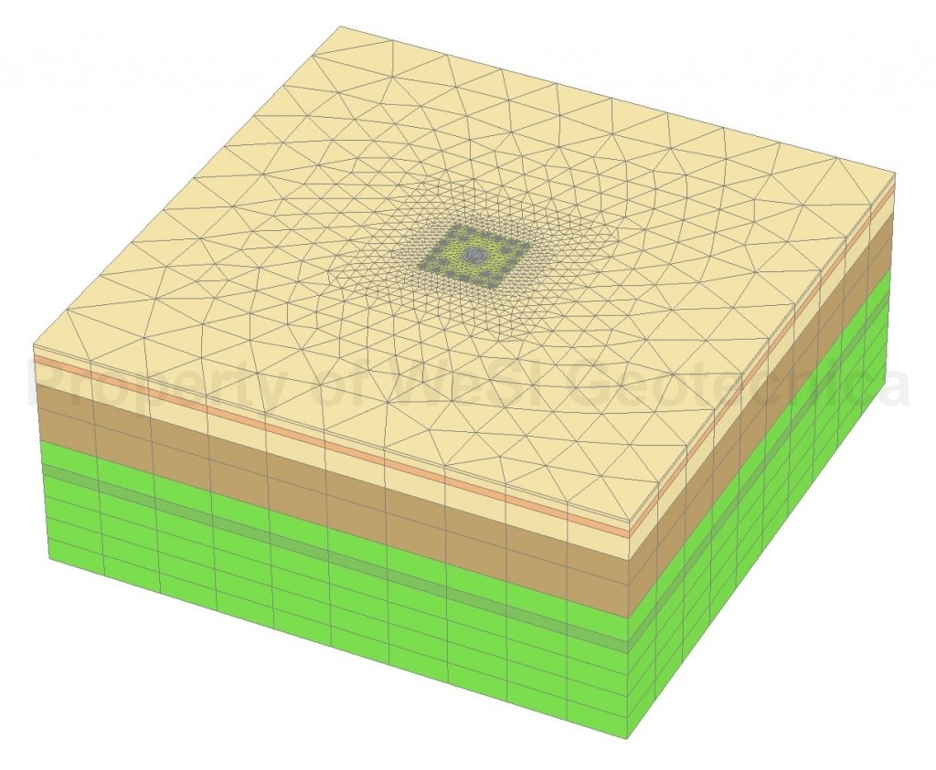
Whenever the soil shows excessive compressibility or poor strength properties, ground improvement configures as a convenient alternative to deep foundations. It consists in the improvement of soil properties near the surface in order to allow shallow foundation to act as feasable geotechnical solution. Ground improvement techniques can vary according to the regional practice, the specialist contractor, the type of soil to treat. The most widespread are vibrocompaction or dynamic deep compaction for loose sands and vibroreplacement stone columns or deep mixing for fine soil deposits. For each of those techniques one or more design methods have been put forward, mostly based on a axisymmetric geometry to model soil interaction. Settlements are often calculated by using linear elastic assumption or empirical methods.
 Design approach
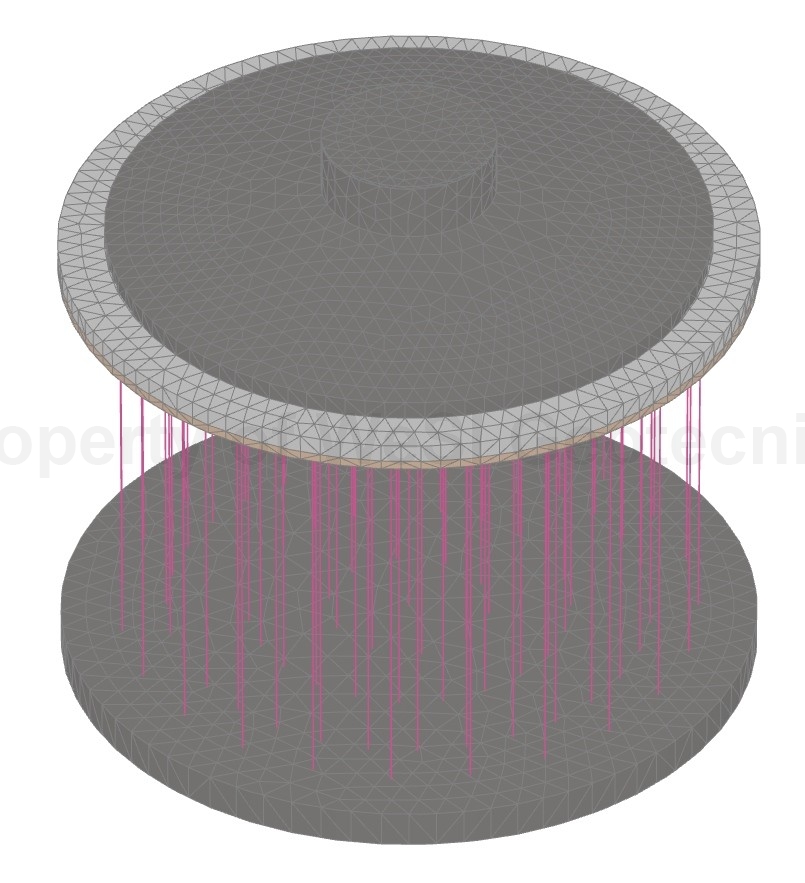
As soil deformability is usually the motivation for using ground improvement, after its inception the Finite Element Method soon became a relevant tool for design. With the limitations related to early computer capacities, important geometrical simplifications were usually being implemented in order to reduce computational effort, such as bidimensional equivalent models or average volume methods. The main drawback of the use of those simplified models was mainly related to calibration, as both geotechnical and hydraulic aspects are very relevant to the case. The numerical specialist had then to select which of the two had to be preferred, and drive the equivalent model accordingly. Nowadays the increased computational capabilities, along with the introduction of numerical tools such as embedded elements, allow the use of full three-dimensional finite element analysis in which the main concern is moved from modelling issues to soil interaction. A field testing campaign along with an accurate soil characterization is what is generally needed in order to calibrate shear interfaces between rigid inclusions and the surrounding soil. Another advantage in using ground improvement techniques is that, whenever stiff permeable inclusions are chosen, they act as drains thus accelerating primary consolidation and making the combined use of preloading particularly efficient. Furthermore, advanced constitutive models are available to capture viscous behaviour (creep) of soft soils. Creep deformations are usually delayed in time and they continue many years after construction. As they might compromise the performance of the ground improvement, creep behaviour of soft soils should be incorporated in an accurate design.
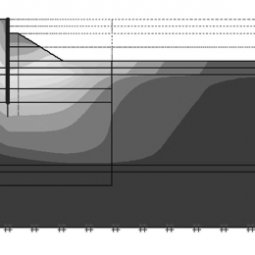
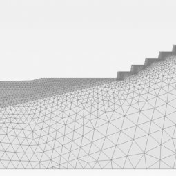
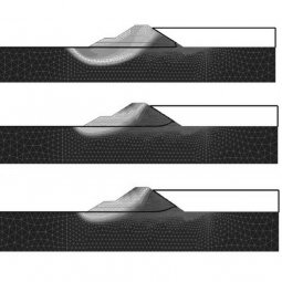
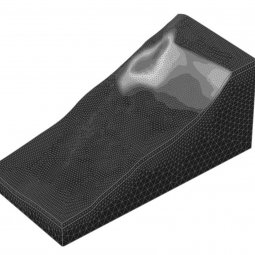
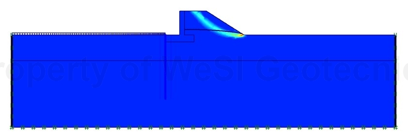
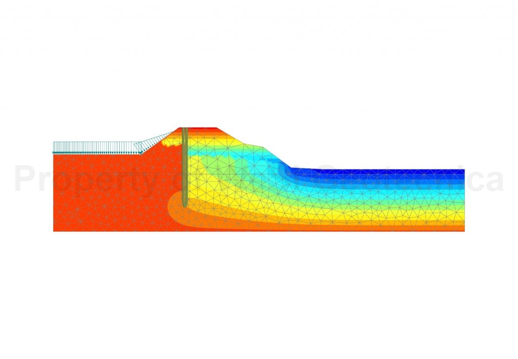
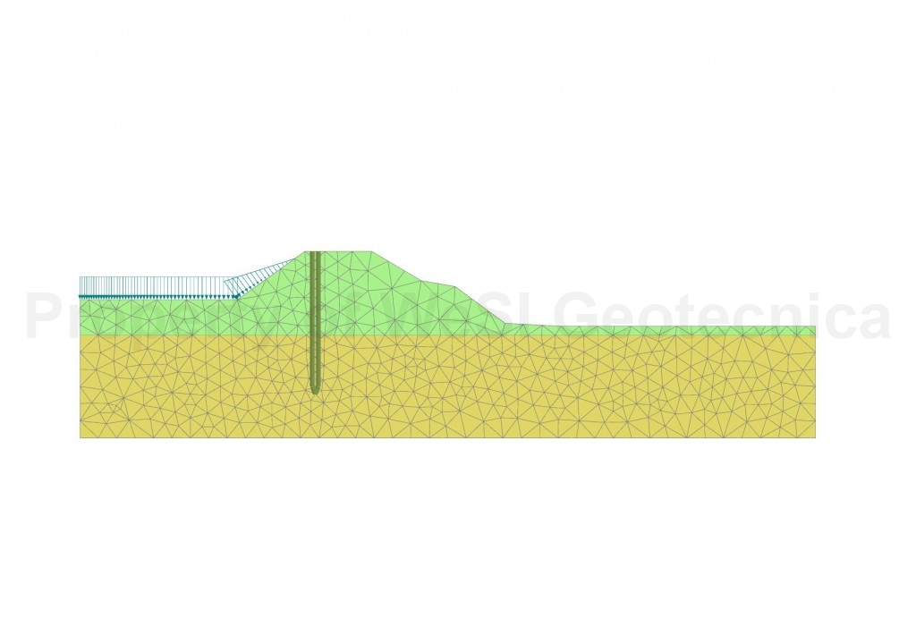
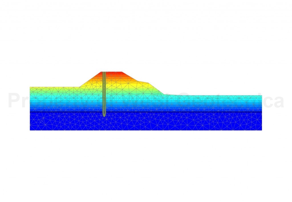
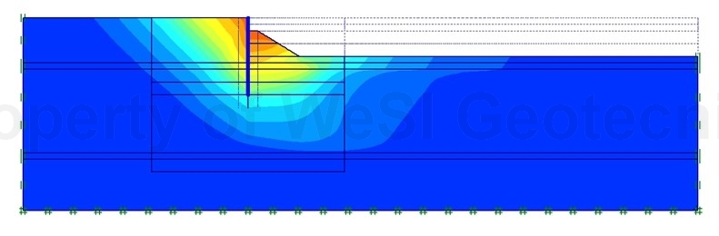
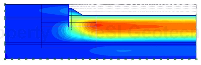
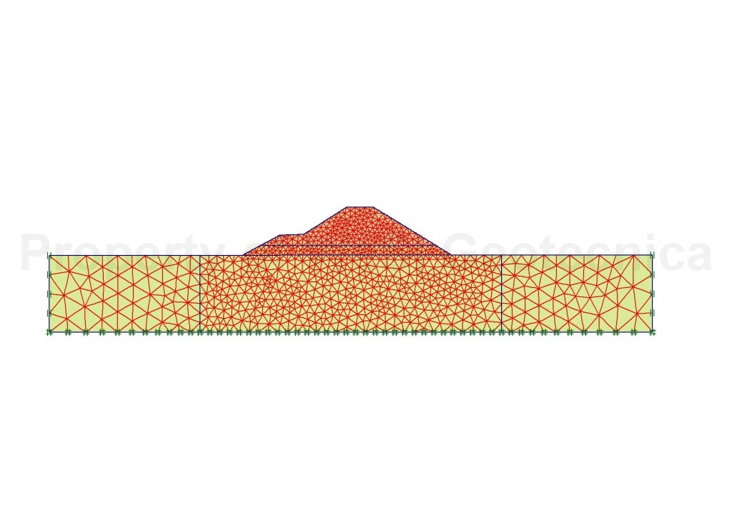
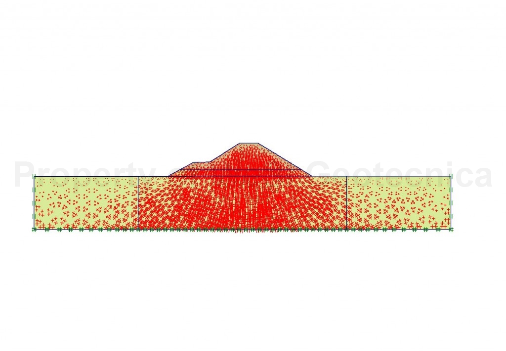
The cross section of an embankments is usually very simple. However the materials involved may vary widely, with foundation soils ranging from soft clays to hard rocks and fills varying between compacted clays to engineered granular fills. The purpose for construction may also vary, as embankments may be used for water retention, from simple flood protection embankments to large embankment dams, as approach to bridges, support for structures,such as roads and railways, amongst others. Embankments used for water retention may incorporate a clayey core, whereas road embankments are usually made of compacted geomaterials sometimes including geotextiles at the base to help spreading the load especially when the structure is founded on improved ground.
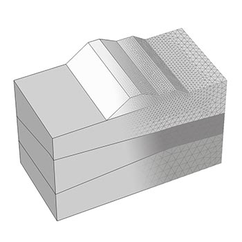 Design approach
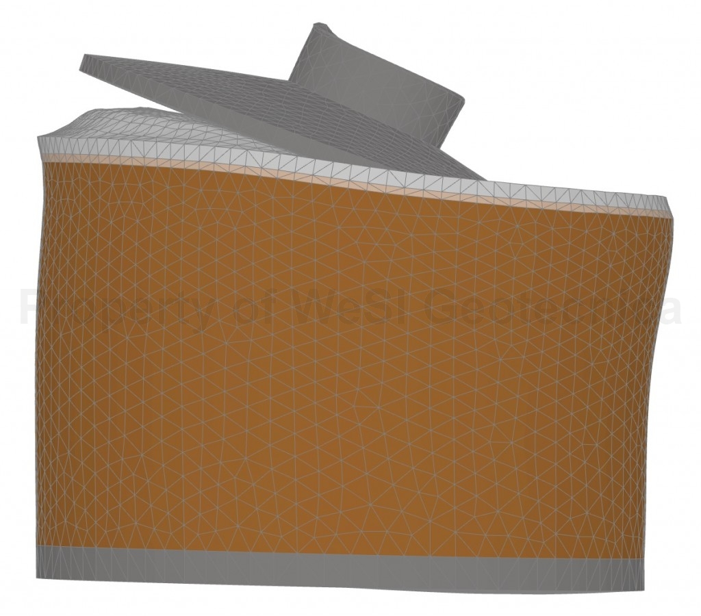
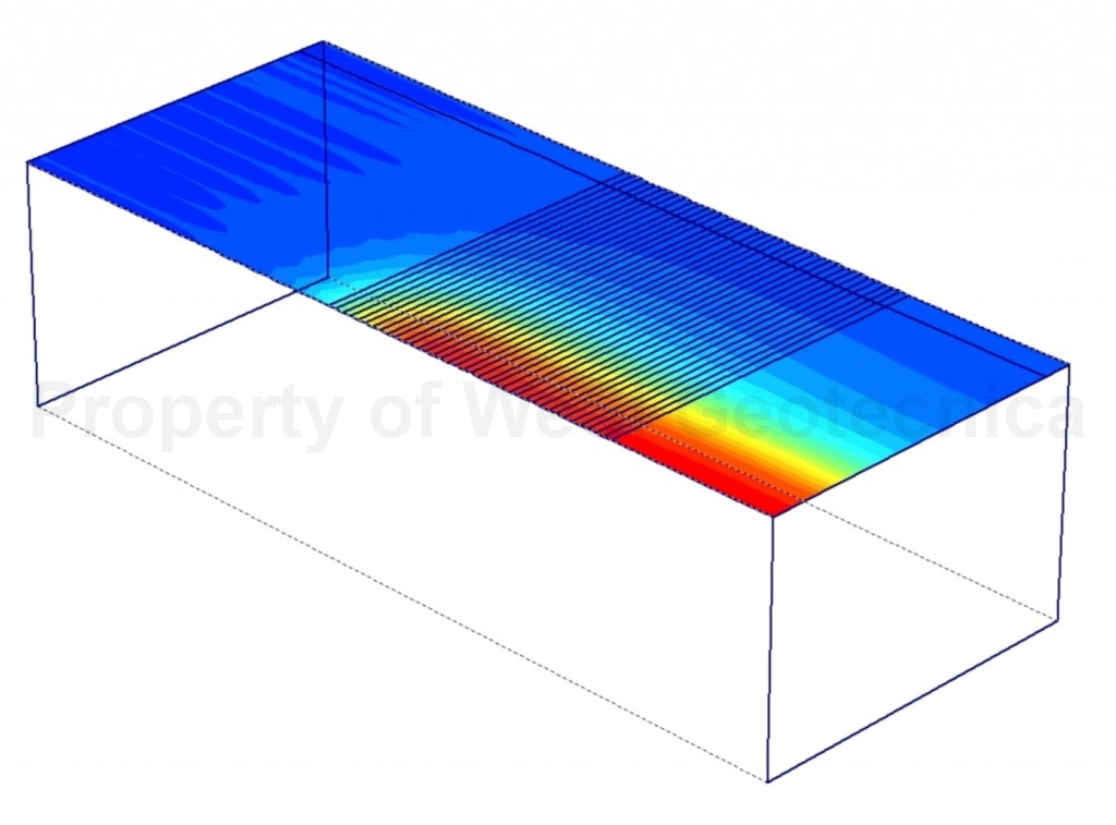
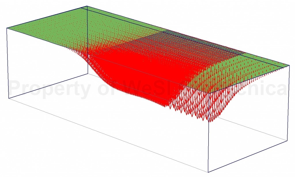
The mechanisms involved in the embankment behaviour can be straightforward, as in the case of non-water retaining embankment of permeable granular fill, or much more complicated, as in the case of low permeability fills placed on a clayey foundation. The construction period of an embankment is typically relatively short compared to the applied surcharge, with no significant excess pore water dissipation in the case of a low-permeabilty compacted fill. It is somehow evident that processes such as consolidation or seepage require the use of Finite Element Method, in particular for the analysis of transient condition in which the pore pressure decreases towards the final value and the available soil resistance needs to be calculated accordingly. Numerical methods can also help in investigating all the possible stress paths, overcoming the geometrical limitations of the traditional design restricted to the axys of symmetry for the settlement calculation, and to a plane strane analysis for slope stability. Through numerical analysis, by making use of appropriate viscous model, it is possible to take into account creep behaviour of soft clays. One dimensional laws obtained by integrating differential equations of primary and secondary consolidation, cannot be used as design tool, if not in very rare conditions where the 1D simplification is acceptable. In the most majority of cases only a plane strain or full 3D numerical analysis of the embankment enables a reliable prediction of long term settlements. Failing to do so may lead to severe design mistakes as witnessed by, among many others, the case of Kansai International Airport.
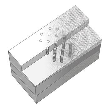
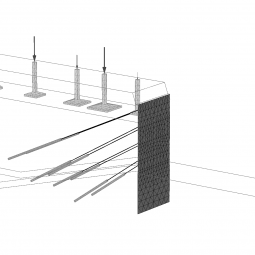
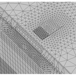
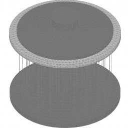
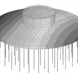
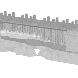
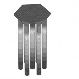
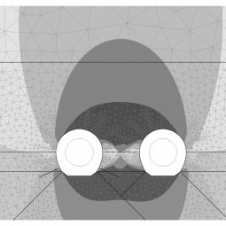
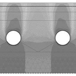
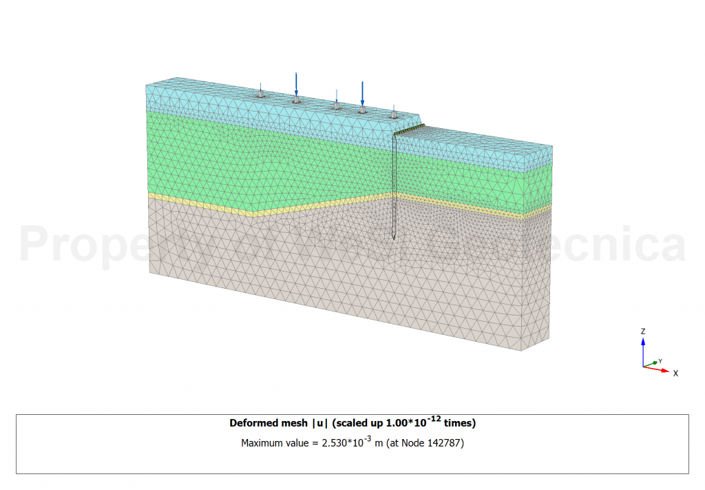
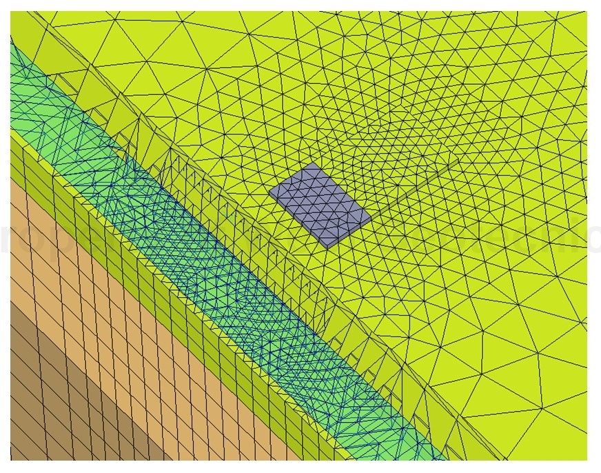
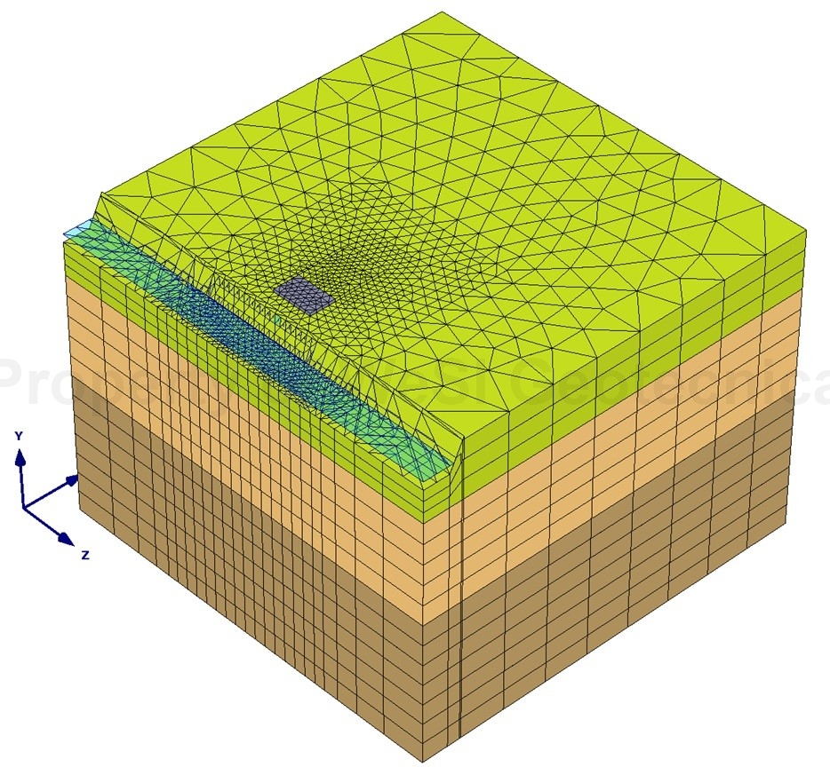
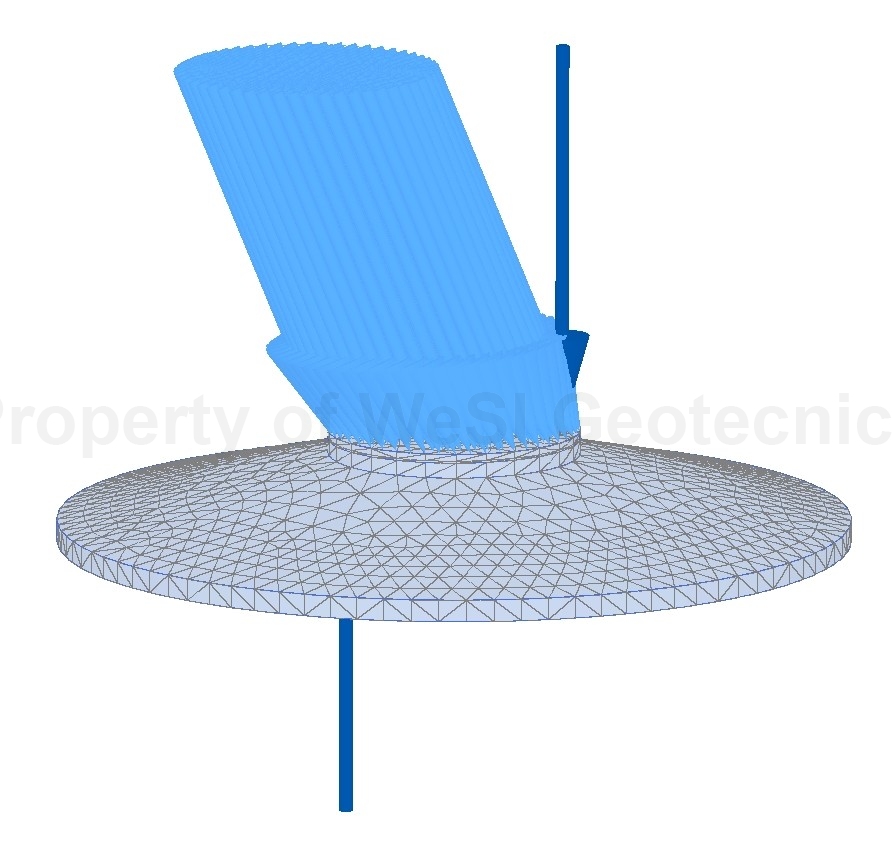
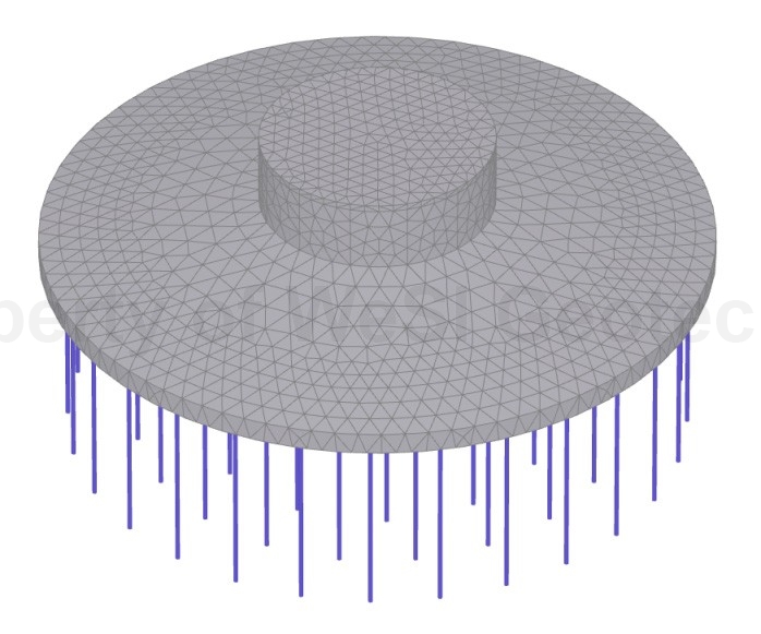
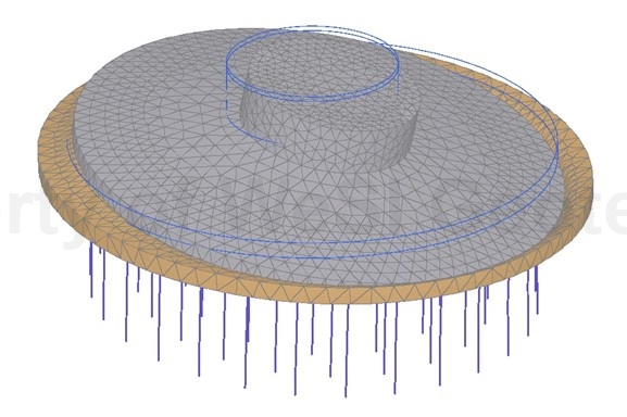
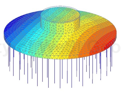
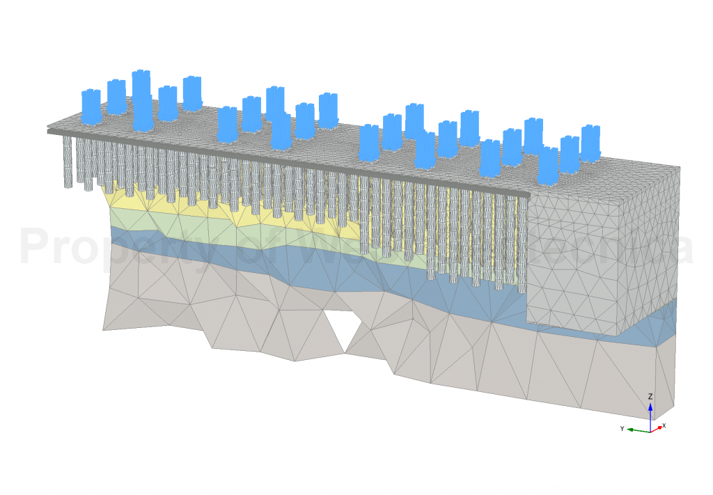
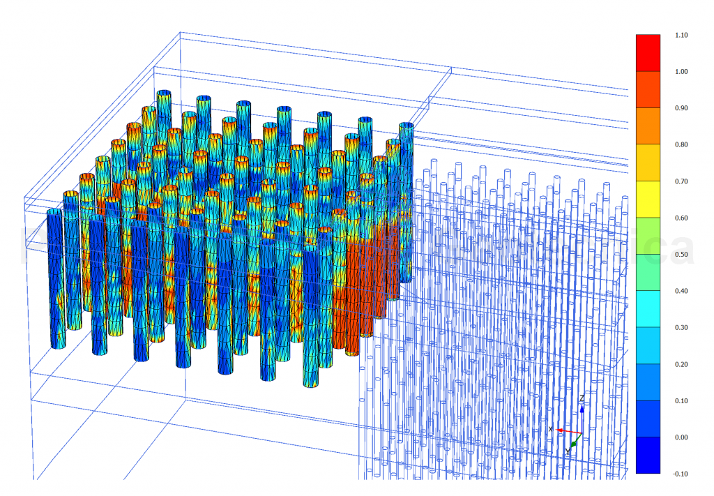
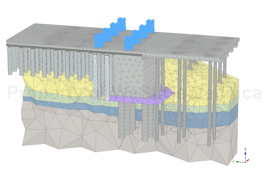
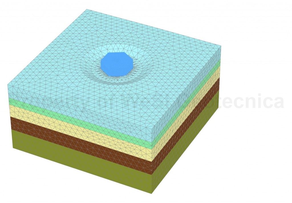
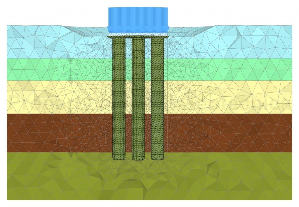
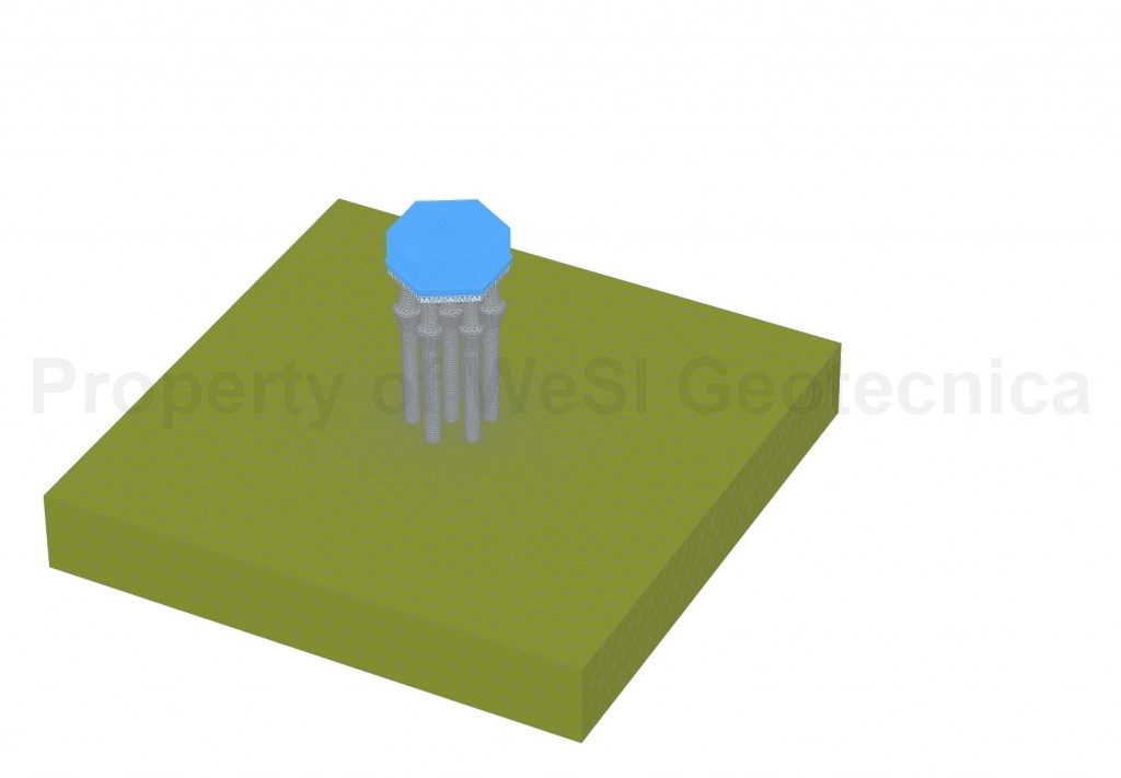
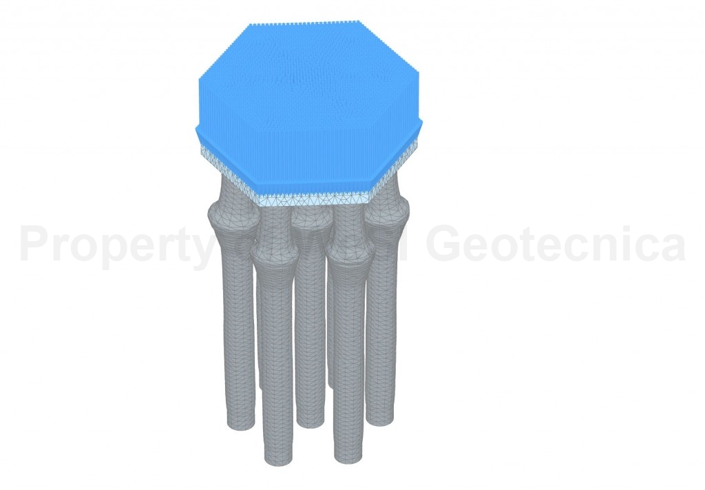
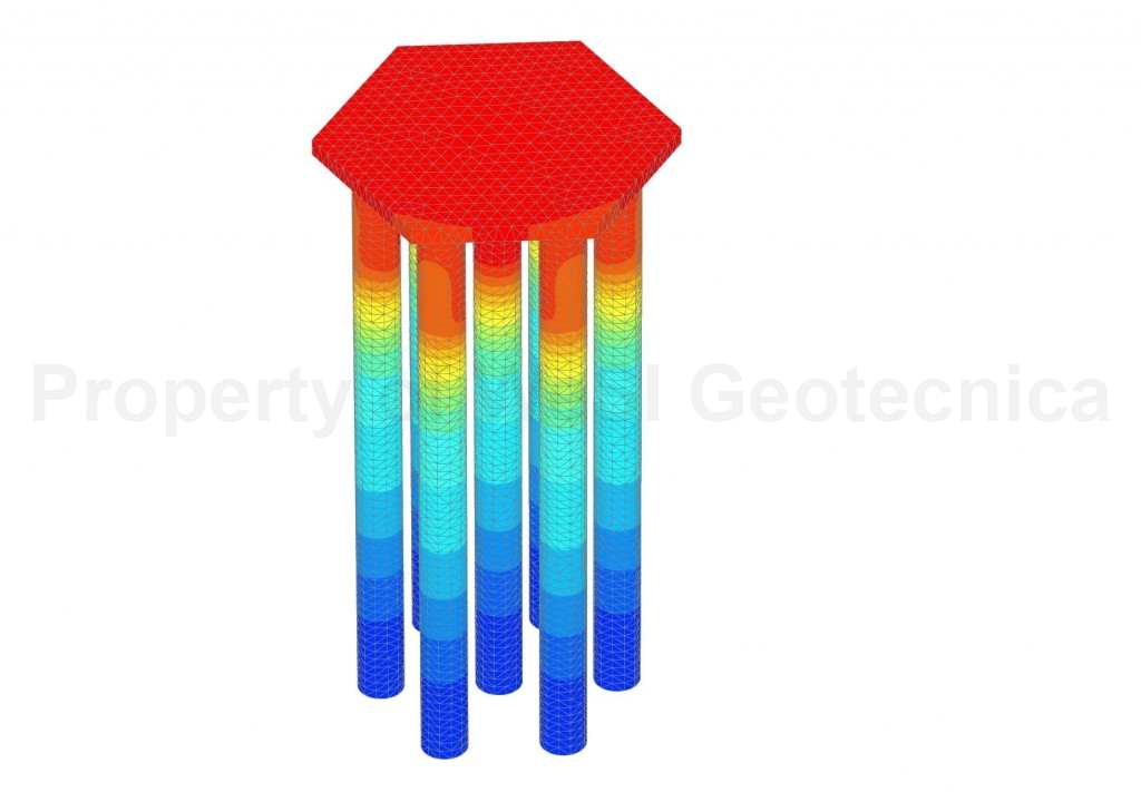
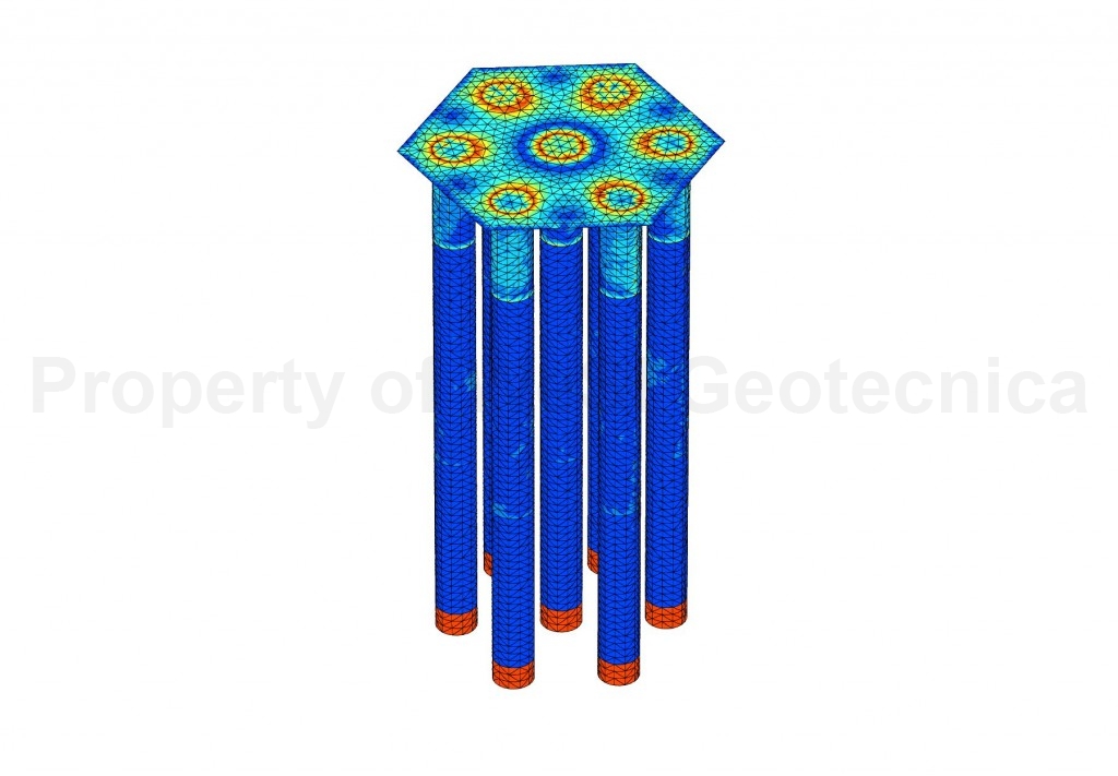
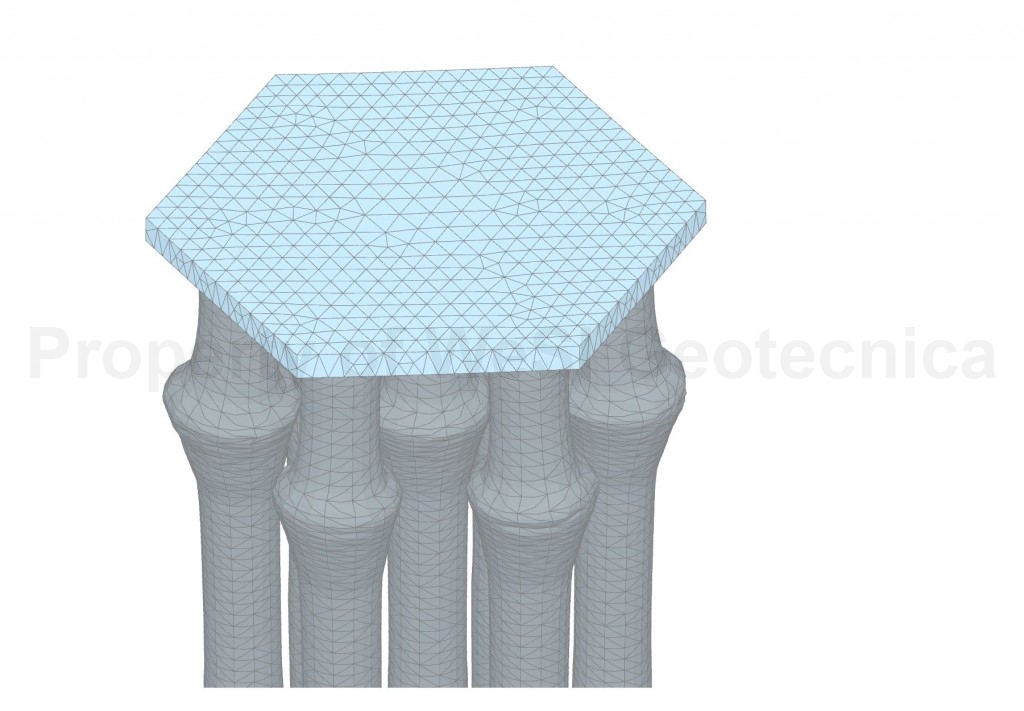
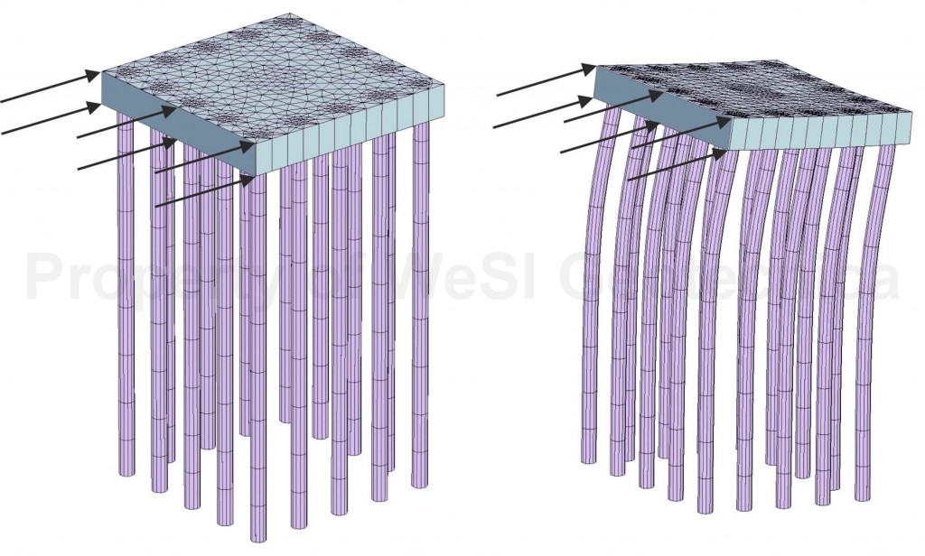
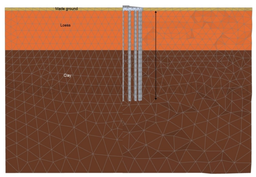
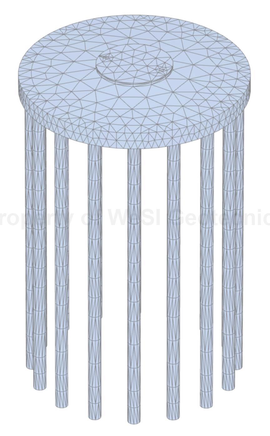
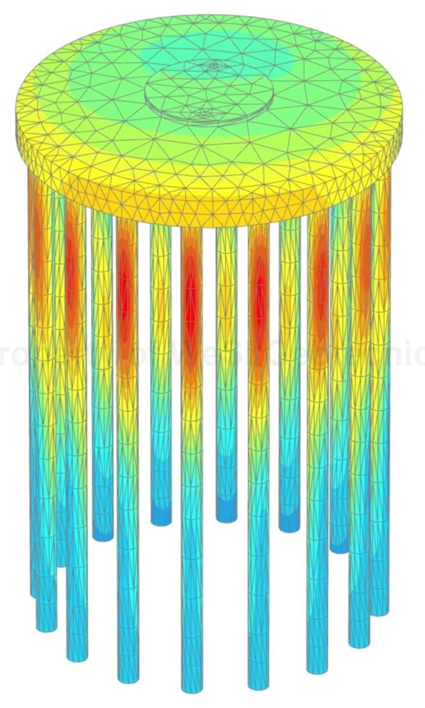
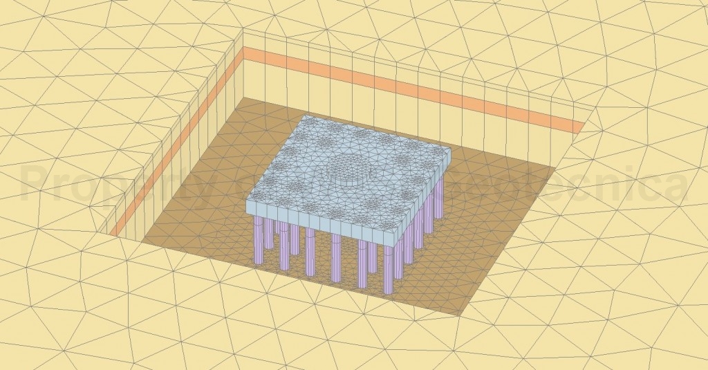
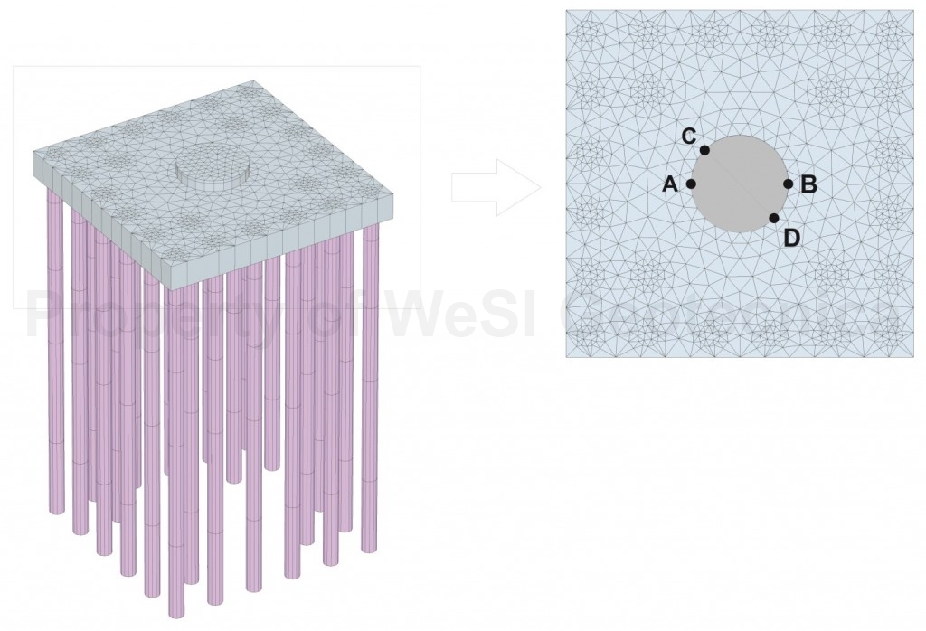
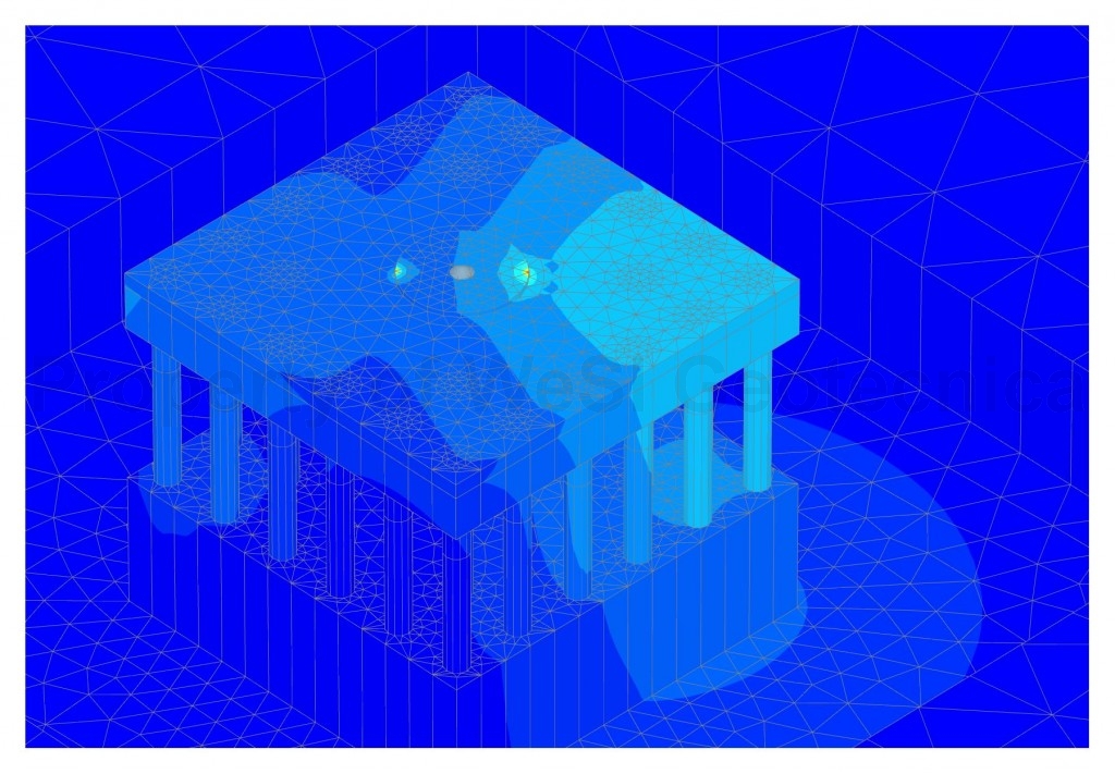
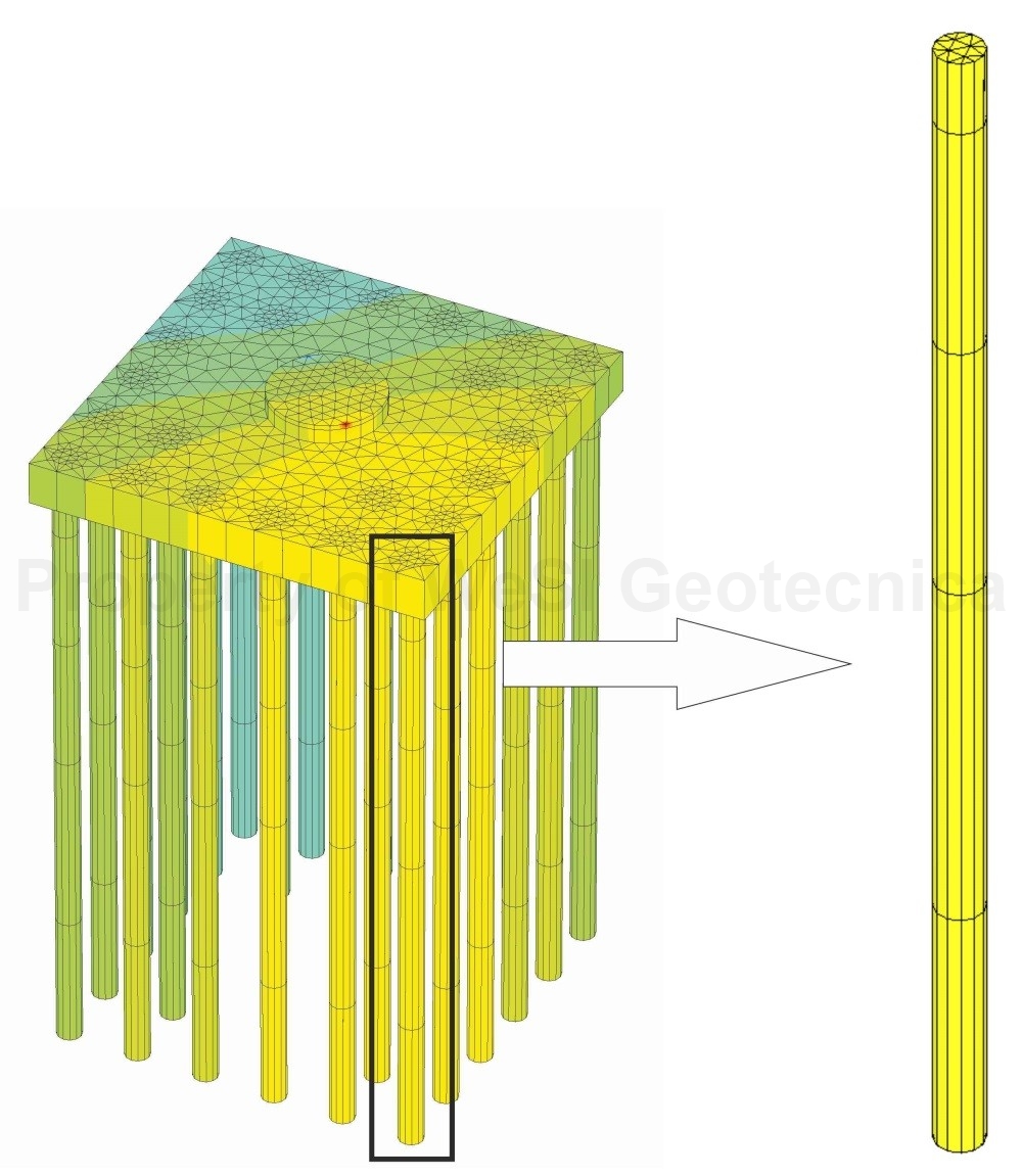
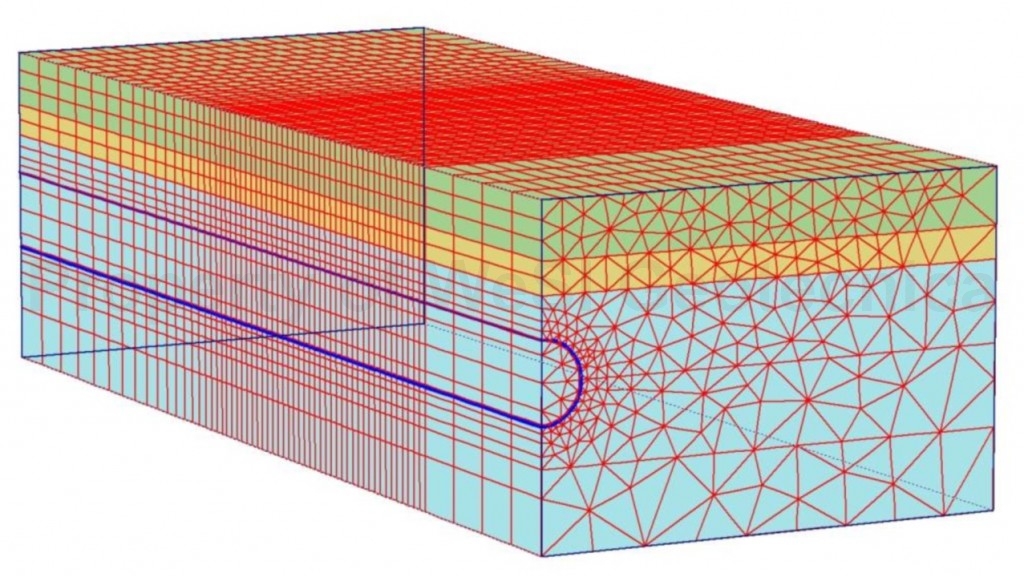
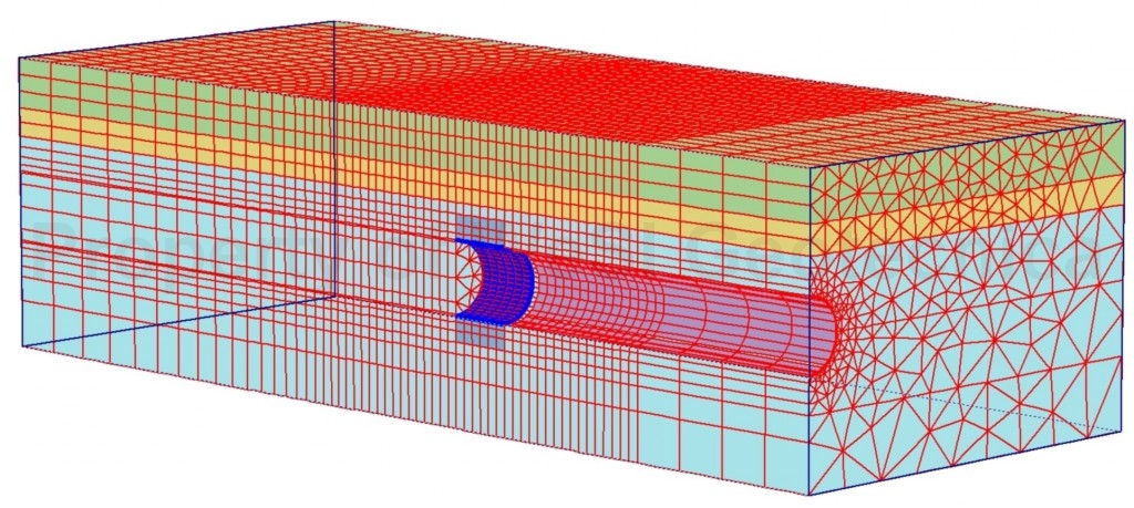
If the soil near the surface is incapable of adequately supporting the structural loads, piles or other forms of deep foundations such as piers or caissons, are used to transmit the loads to suitable soil or rock at greater depth. Piles can be divided into categories according to their methods of installation, mainly referring to soil displacement and disturbance. The bearing capacity of a pile is being traditionally determined by either analytical or semiempirical methods. Evidence from load tests on instrumented piles shows that in the inital stages of loading, most of the load is supported by skin friction on the upper part of the pile. As the load increases, further mobilization of the skin friction takes place along with base resistance. However, as the vertical displacement of the pile needed for full mobilization of the base resistance is significantly larger than the one required to mobilize shaft resistance, design engineers usually apply different partial factors for the two terms, without being able to fully capture this load-transfer mechanism. Similar procedure applies to pile groups, where empirical procedures are used in order to obrain group bearing resistance starting from single pile capacity.
 Design approach
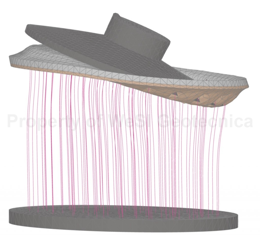
The analysis of a pile group is a three dimensional problem. Current methods of analysis of pile groups are either based on linear elastic soil behaviour or combined of non-linear behaviour for single pile then linear for groups. In general these methods prove too simplistic, or inconsistent in the way they model pile-soil interaction. With the increase of computational capacity, pile group can now included in a full three dimensional finite element analysis. This possibility is more then ever necessary when loading on the pile cap is not vertical or high bending moment is present, and no symmetry assumptions can be adopted. Within a finite element numerical analysis, soil-pile interaction can be taken into account by using appropriate interface elements, able to capture the evolution in the load-transfer mechanism with depth during loading. However, it is generally recommended to calibrate the single pile response by using an in-situ load test.
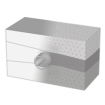
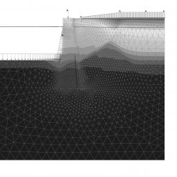
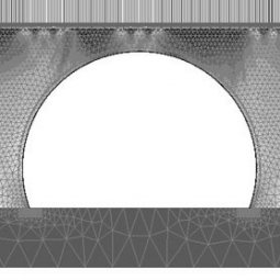
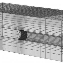
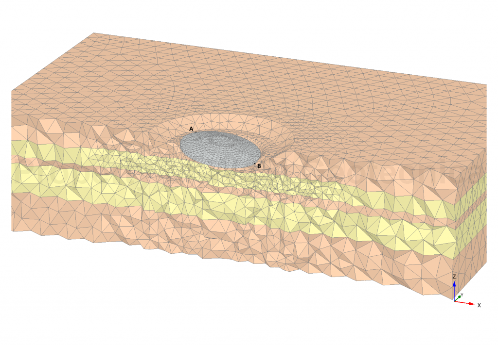
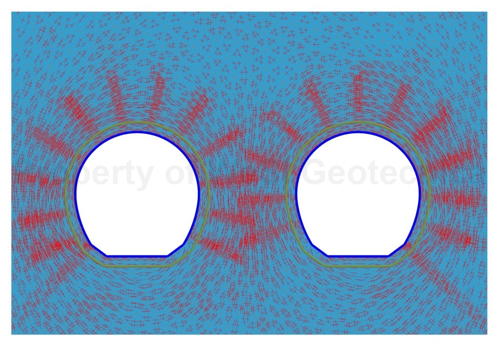
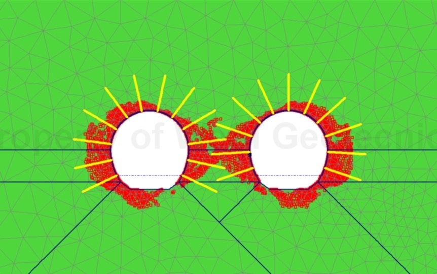
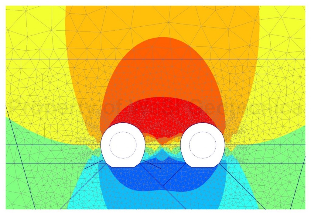
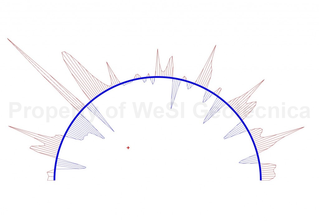
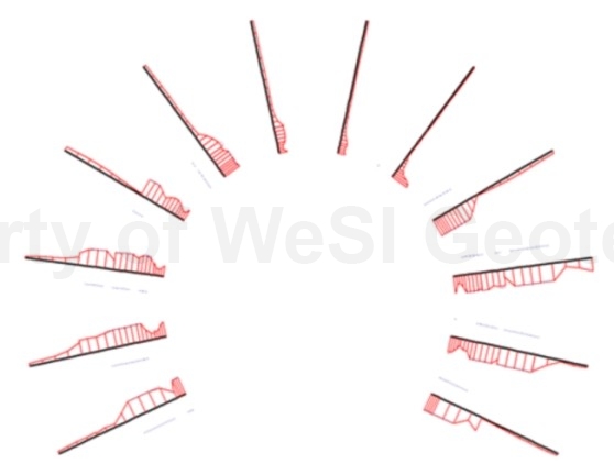
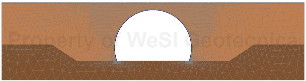
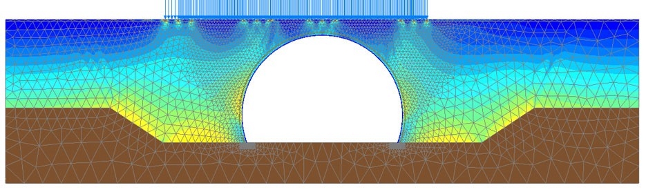
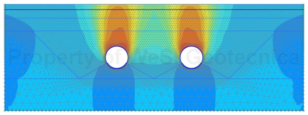
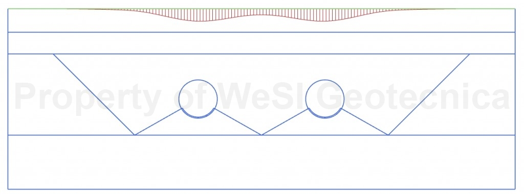
Conventional economic tunnel design generally addresses structural collapse and ground deformations as main criteria to be investigated. Nowadays, civil engineering construction comes with many alternative methods for tunnelling: the permanent support is provided by several means and so the temporary support when needed. The decision upon which construction sequence to adopt is mainly based on the geology of the site and on the size or shape of the required excavation. Traditional design methods have to be selected according to different opening procedures, preliminary and permanent lining types and different ground behaviour.
 Design approach
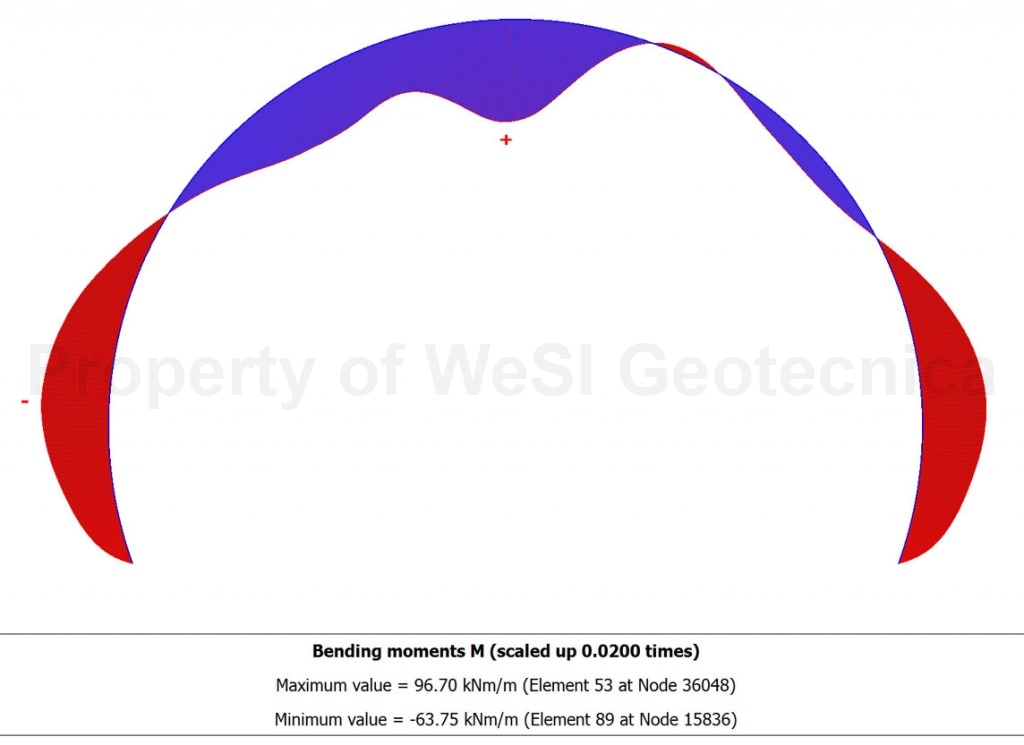
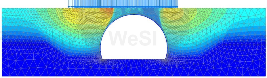
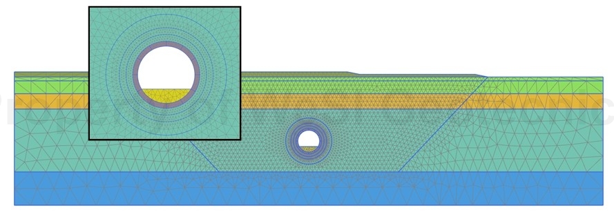
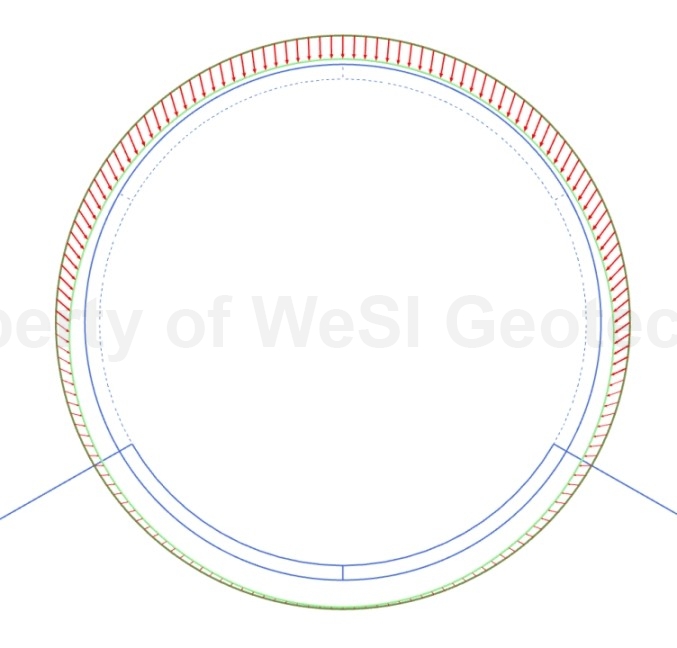
Many conventional methods are available in engineering practice for obtaining reasonable estimates of the ground response to the tunnel excavation and the likely loads applied to the implemented supports. These traditional design procedures may probably appear as a straightforward application within the design process. But they are unfortunately intrinsically uncoupled: in fact the loads are typically determined by elastic solutions while ground movements are based on empirical methods, the two aspects not being linked together. Furthermore, information gained from traditional calculations is often limited and implies strong simplifications in the geotechnical model: for instance predictions are limited to greenfield situations, without any influence to ground displacements coming from existing structures or services. In contrast with conventional design methods, the numerical procedures can be successfully adopted for the analysis of such complex problems. First of all Finite Element Method can deal with complex ground conditions, e.g. sloping ground layers or three dimensional geometries, as in the case of tunnel junctions. Realistic soil behaviour involving plasticity, complex hydraulic conditions, short and long term conditions and non-conventional boundaries can all be modelled by using numerical methods. Finite Element Method can handle the presence of adjacent services and structures or articulated construction sequences, sometimes involving ground treatment (e.g. compensation grouting). Opening and support construction has a significant effect on predicted ground deformations and lining forces. Therefore, different installation procedures can be simulated according to the tunnelling method through a correctly defined ground-lining interaction.
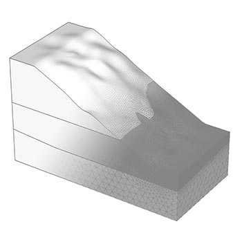
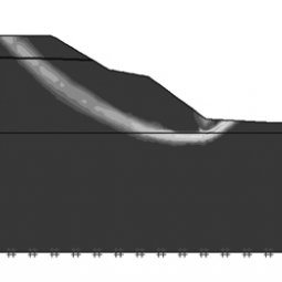
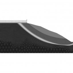
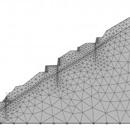
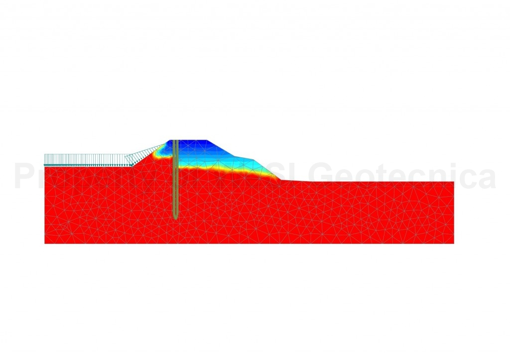
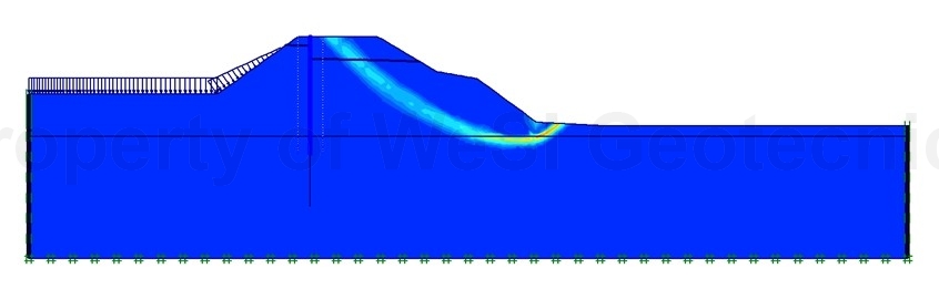
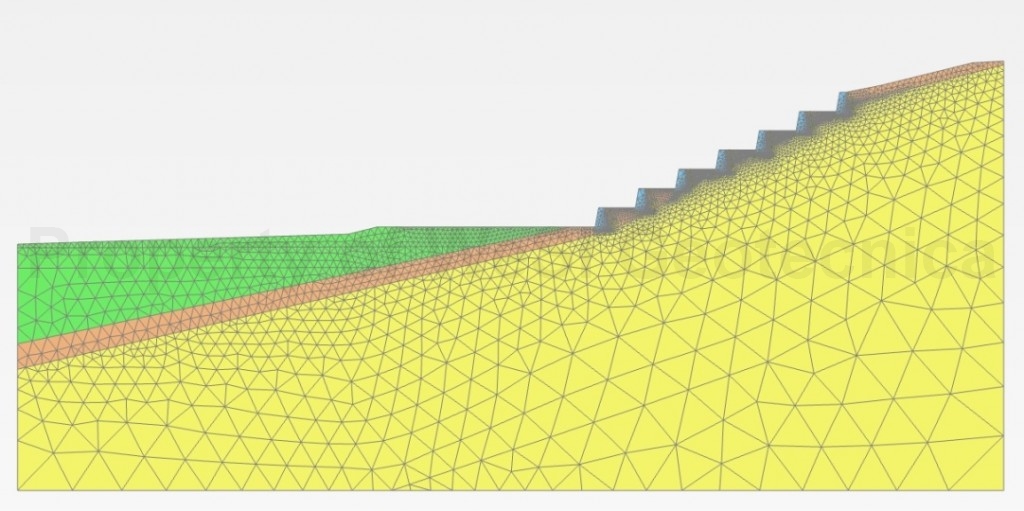
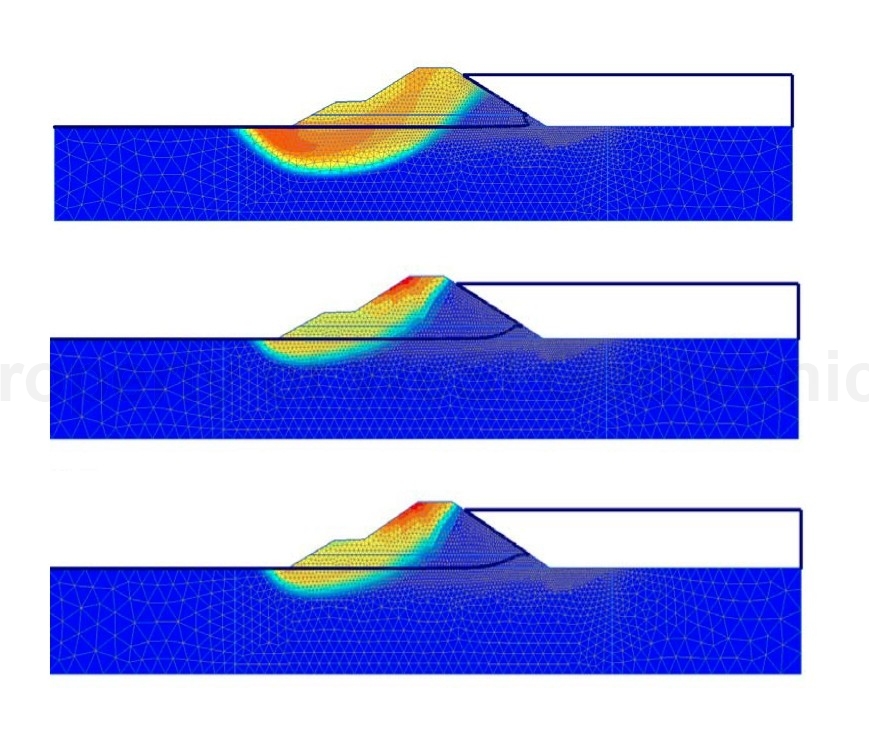
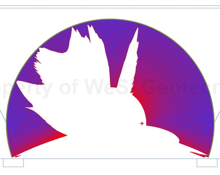
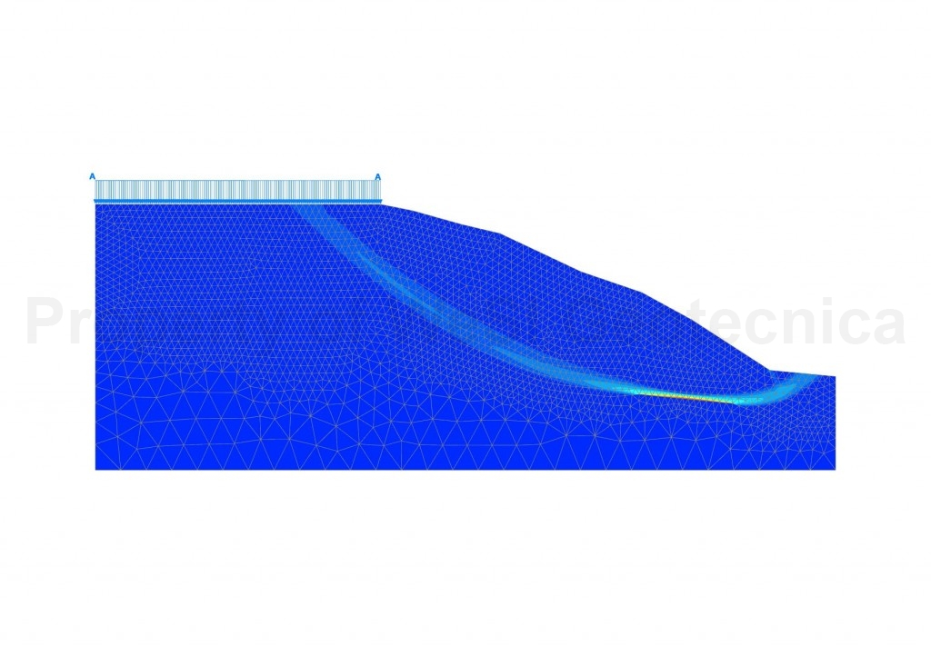
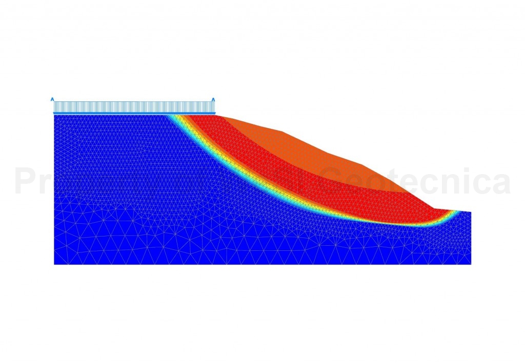
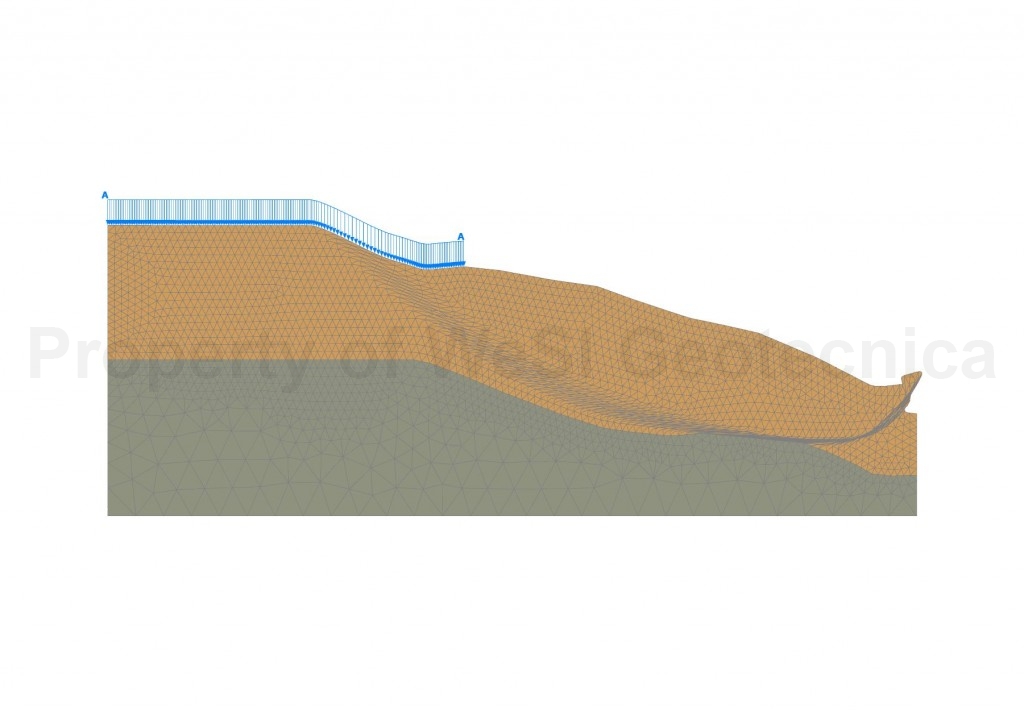
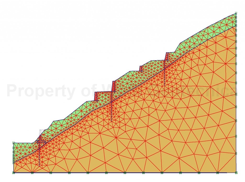
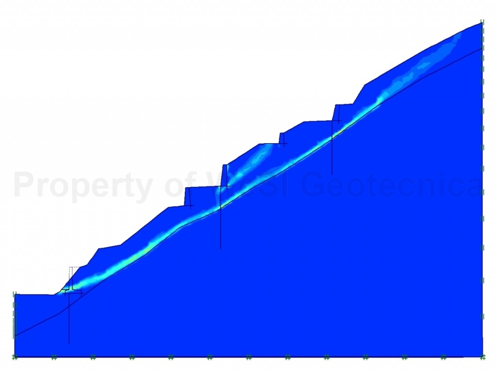
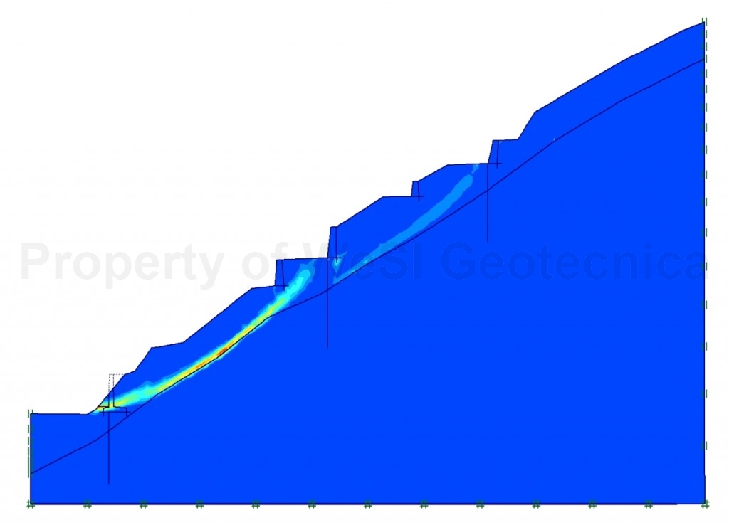
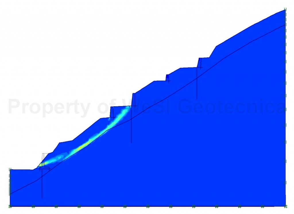
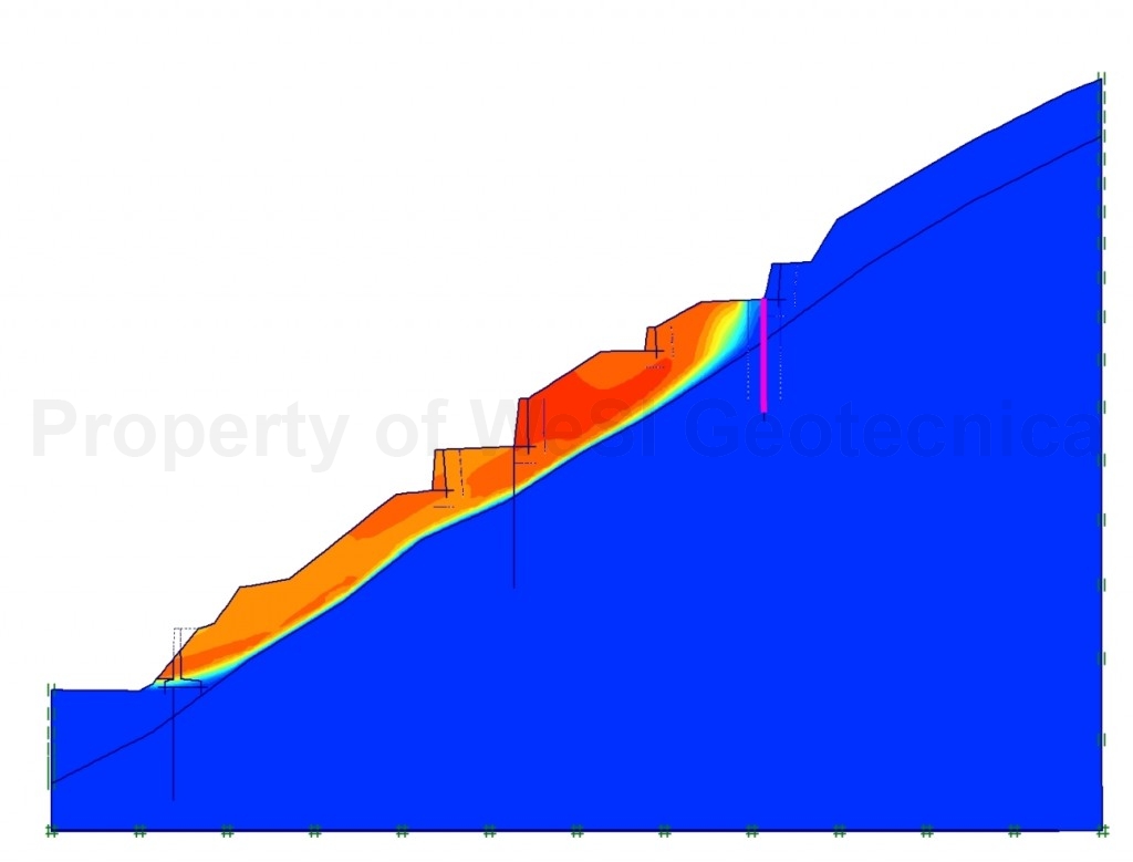
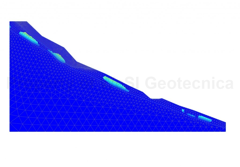
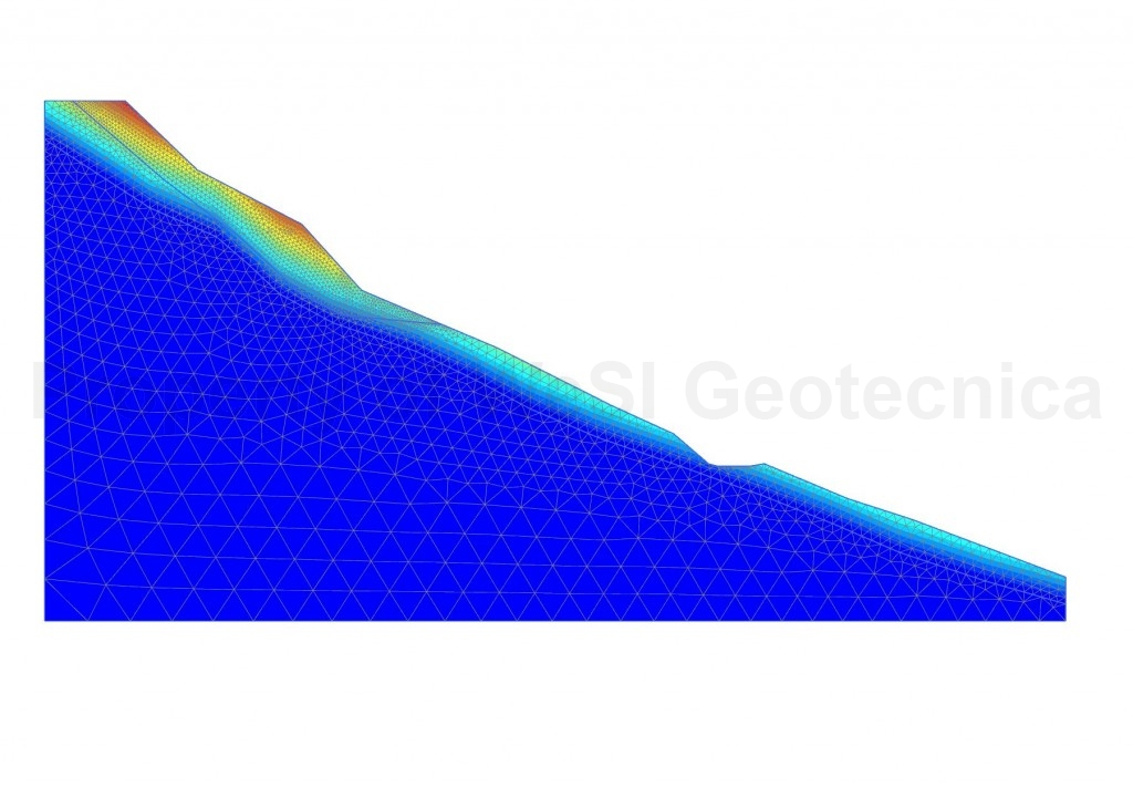
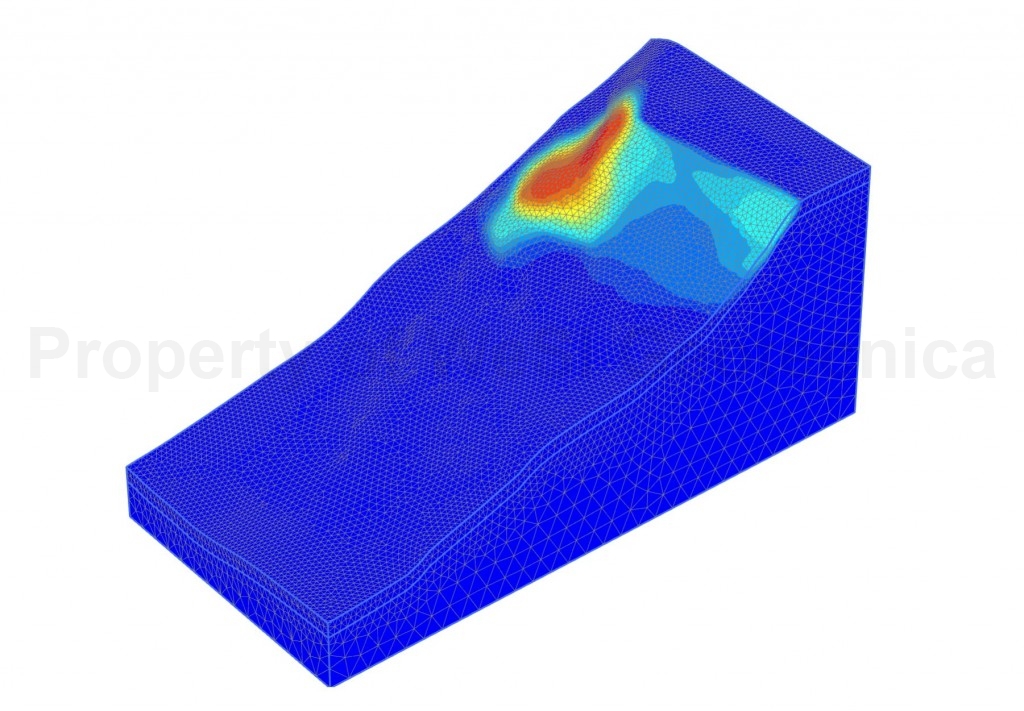
Gravitational and seepage forces tend to cause instability in natural and man-made slopes. The most important types of failure mechanisms include circular and non-circular rotational, translational and compound slips, depending on ground layering. Traditional design is generally focused on stability rather than displacement. When the deformation field is such that the strains involved exceed the value corresponding to peak strength, the strength drops towards its constant volume value. In case of a pre-existing slip surface, the use of residual strength values might be appropriate. In most cases slope stability can be considered a two-dimensional problem, thus assuming plane strain conditions. Limit Equilibrium Method is normally used in slope stability analysis by considering families of possible failure surfaces. The factor of safety is then assumed as the lowest value amongst those calculated for each family.
 Design approach
A basic distinction in the analysis based on Limit Equilibrium Method is between short and long term conditions. It is usually assumed that undrained conditions prevail in the short term, implying total stress calculations for fine-grained soils, while effective stress analysis is typically performed for the long term when all the excess pore water pressures have dissipated. Intermediate situations cover the period between short and long term. Unfortunately, the pore water pressure distribution during this transient state cannot be easily calculated, and it is therefore difficult to adopt an effective stress stability analysis. Finite element analysis can simulate consolidation or swelling by predicting the pore pressure dissipation over time; if needed, it can model the mechanism of progressive failure by incorporating strain-softening laws, as well as plastic straining during excavation for normally consolidated soil. All these and other features come without any need for a pre-determined slip surface, proving useful in all those situations where engineering judgement is not straightforward, or where complex three-dimensional geometry make the use Limit Equilibrium Method unsafe. In particular, whenever necessary, the construction sequence can be taken into account and reproduced in the analysis. The design engineer is then able to predict the evolution of the critical surface, and not restrained to the evaluation of the factor of safety.
WeSI Geotecnica Srl
Piazza de Gasperi, 15/11
54100 Massa (MS) - Italy
Tel. +39 0585 44824
Via Sottoripa, 1A/121
16124 Genova (GE) - Italy
Tel. +39 010 0981550
email: info@wesigeotecnica.it


__large-watermark.jpg)
consolid__large-watermark.jpg)
__large-watermark.jpg)